Method of repairing a stationary shroud of a gas turbine engine using laser cladding

a gas turbine engine and laser cladding technology, which is applied in the direction of machines/engines, blade accessories, metallic material coating processes, etc., can solve the problems of oxidation, corrosion, abrasion of the gas path surface and the metal of the stationary cladding is typically not highly resistant, so as to improve the service life and reduce the process variation. , the effect of improving the service li

Inactive Publication Date: 2007-09-06
GENERAL ELECTRIC CO
View PDF11 Cites 19 Cited by
  • Summary
  • Abstract
  • Description
  • Claims
  • Application Information

AI Technical Summary

Benefits of technology

[0012] The present invention is an advancement of the technology for repairing and restoring shrouds for engine service. Unlike stationary shrouds repaired by the TDC process, stationary shrouds repaired in accordance with the present invention are not temperature-limited because of additions of melting point depressants such as boron or silicon. The present invention is also an advance over low pressure plasma spraying (LPPS) since no partial vacuum is required during the deposition of the restoration, making the present process faster, cheaper, more effective and easier to perform. Other advantages include less process variation and no preheat. Very importantly, there is much less part distortion, so that the ability to restore the shroud to the original drawing tolerances can be done more easily and with less machining. The present approach provides achieves results superior to ADH, because the stationary shroud is restored to its original dimensions using a structural material, rather than the rub-resistant coating. The rub-resistant coating is preferably applied over the dimensionally restored base metal of the stationary shroud.

Problems solved by technology

The gas path surface of the stationary shroud is exposed to abrasion by the rotating turbine blade tips and also to erosion, oxidation, and corrosion by the hot combustion gases.
The base metal of the stationary shroud is typically not highly resistant to the environmental attack and abrasion, and therefore an environmentally resistant rub coating is applied on the gas path surface of the stationary shroud.
Over a period of time as the engine operates, the surface of the environmentally resistant rub coating is worn away, and some of the base metal of the stationary shroud may also be damaged and / or removed.
At some point, the stationary shroud is no longer operating acceptably and the operation of the gas turbine degrades below acceptable levels.
The first three approaches restore the stationary-shroud dimensions using the rub-resistant coating material but do not restore the structural strength of the underlying shroud base metal.
The stationary shroud no longer has its necessary mechanical properties, so that there is a risk of mechanical failure of the stationary shroud.

Method used


Image

  • Method of repairing a stationary shroud of a gas turbine engine using laser cladding
  • Method of repairing a stationary shroud of a gas turbine engine using laser cladding
  • Method of repairing a stationary shroud of a gas turbine engine using laser cladding

Examples


Embodiment Construction

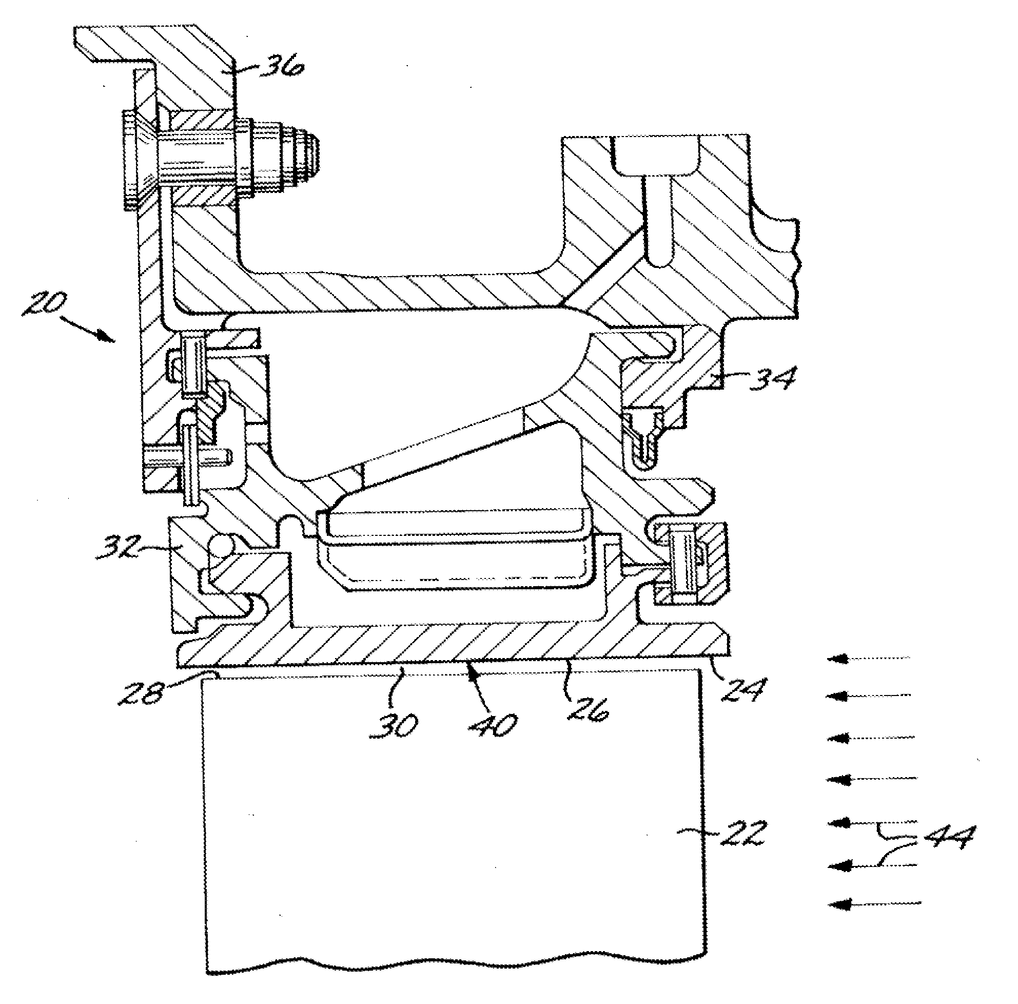
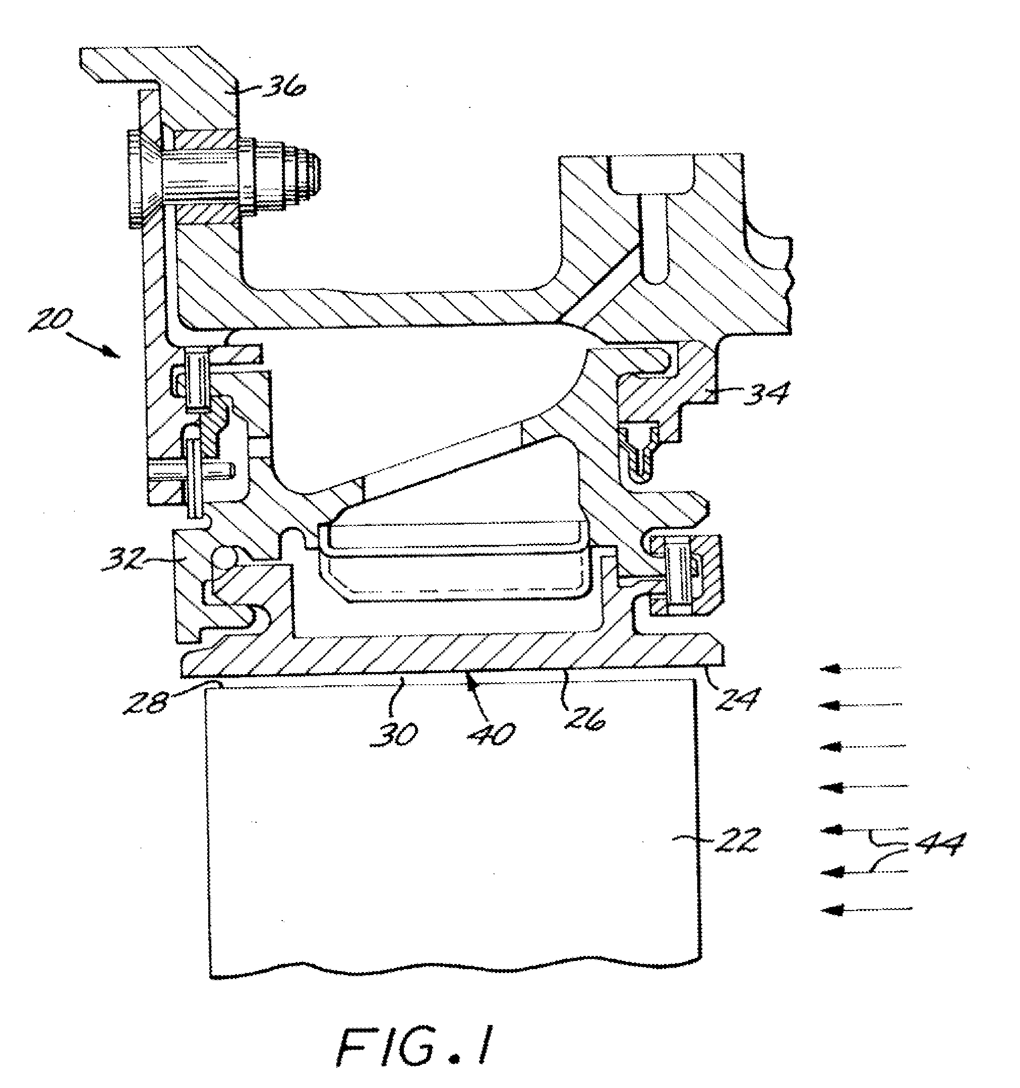
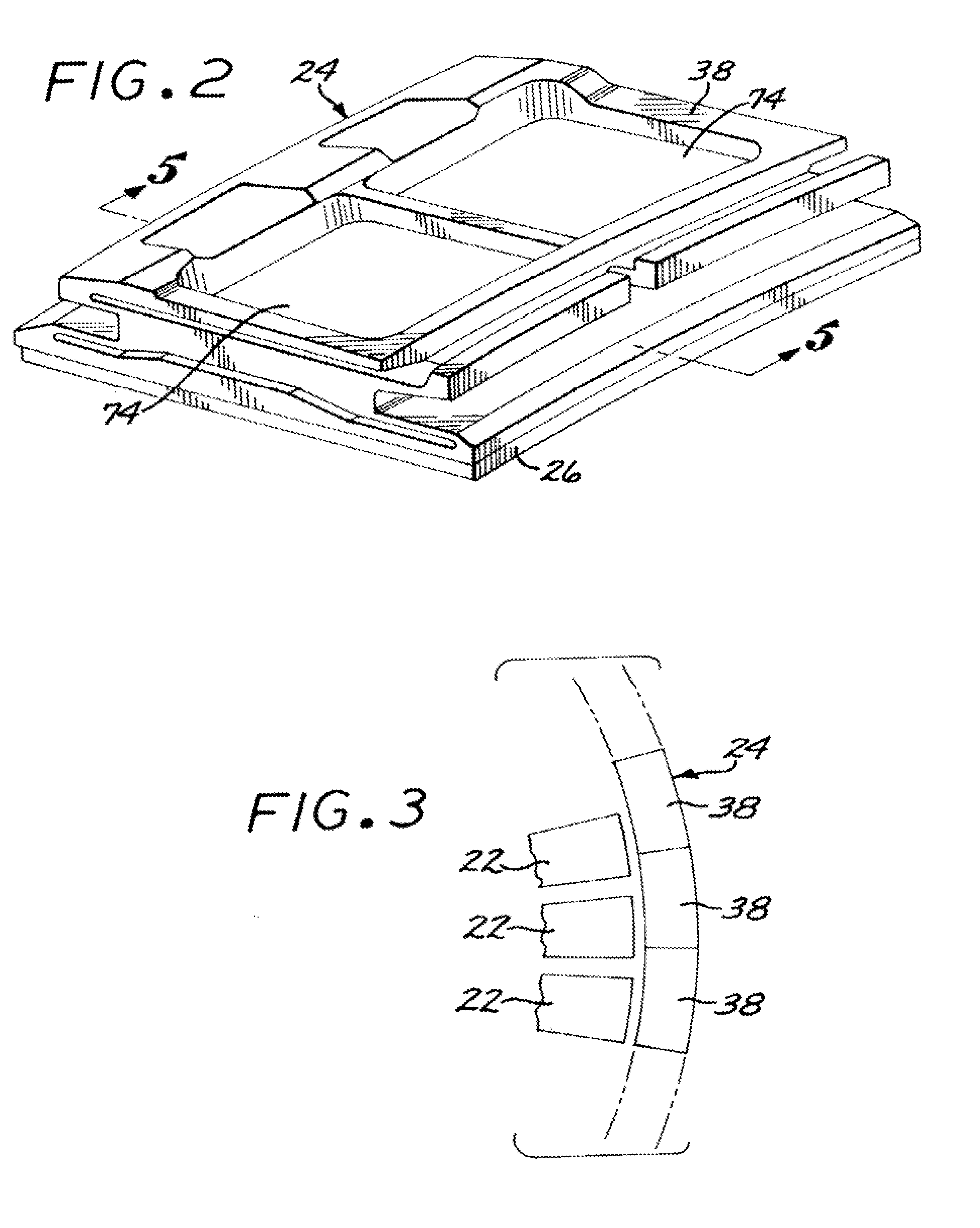
[0022]FIG. 1 is a cross-sectional view generally depicting a stationary shroud assembly 20 in relation to a turbine blade 22. The stationary shroud assembly 20 includes a stationary shroud 24 having a flow-path surface 26 in a facing relation to a turbine blade tip 28 of the turbine blade 22. (The term “stationary shroud” as used herein refers to structure which does not rotate as the turbine blade 22 turns with its supporting turbine disk (not shown) and turbine shaft (not shown). The stationary shroud 24 is to be distinguished from the rotating shroud that is found at the tip of some other types of blades and is a part of the blade, and which does not rotate as the blade turns.) A small gap 30 separates the flow-path surface 26 from the turbine blade tip 28. The smaller is the gap 30, a less hot combustion gas 44 that can leak through the gap 30 and not participate in driving the turbine blade 22. Also depicted are a stationary shroud support 32 from which the stationary shroud 22...


PUM

PropertyMeasurementUnit
weight percentaaaaaaaaaa

Abstract

A stationary shroud of a gas turbine engine made of a base metal is repaired by removing any damaged material from a flow-path region of the stationary shroud to leave an initially exposed base-metal flow-path surface; and applying a base-metal restoration overlying the initially exposed flow-path surface. The base-metal restoration is applied by furnishing a source of a structural material that is compatible with the base metal, in a form such as a powder or a wire, and depositing the source of the structural material overlying the initially exposed base-metal flow-path surface of the stationary shroud by laser cladding to form a repaired base-metal flow-path surface. An environmentally resistant rub coating may be applied overlying the base-metal restoration.

Description

[0001] This invention relates to aircraft gas turbine engines and, more particularly, to the repair of a stationary shroud that has previously been in service. BACKGROUND OF THE INVENTION [0002] In an aircraft gas turbine (jet) engine, air is drawn into the front of the engine, compressed by a shaft-mounted compressor, and mixed with fuel. The mixture is burned, and the hot combustion gases are passed through a gas turbine mounted on the same shaft. The flow of combustion gas turns the gas turbine by impingement against an airfoil section of the turbine blades and vanes, which turns the shaft and provides power to the compressor. The hot exhaust gases flow from the back of the engine, driving it and the aircraft forward. [0003] In the gas turbine, an annular, circumferentially extending stationary shroud surrounds the tips of the rotor blades. The stationary shroud confines the combustion gases to the gas flow path so that the combustion gas is utilized with maximum efficiency to tu...

Claims


Application Information

Patent Timeline
Patent Type & Authority Applications(United States)
IPC IPC(8): B23K26/20F01D5/28B23K26/00B23K26/34B23K35/30B23P6/00C22C19/05C22C19/07C23C24/10C23C26/02F01D9/04F01D25/24F02C7/00
CPCB23K26/34B23K2201/001B23P6/007C23C24/10C23C26/02B23K35/3046F05D2230/80B23K26/3206B23K26/3213B23K35/3033F01D9/04B23K26/32B23K2101/001B23K2103/26B23K2103/50
Inventor GROSSKLAUS, WARREN DAVIS JR.MILLER, MATTHEW NICKLUS
Owner GENERAL ELECTRIC CO
Why Eureka
Try Eureka