Transmitter, receiver, and transmission/reception system

a transmission/reception system and receiver technology, applied in the field of transmission/reception system, can solve the problems of small power consumption and small size of the transmitter of this transmission/reception system, and achieve the effect of small power consumption and small siz

Inactive Publication Date: 2007-09-06
PANASONIC CORP
View PDF7 Cites 14 Cited by
  • Summary
  • Abstract
  • Description
  • Claims
  • Application Information

AI Technical Summary

Benefits of technology

[0012] A transmission / reception system is adaptable to be used for an encapsulated endoscope that can be swallowed by a living organism. The system includes a transmitter and a receiver. The transmitter includes a voltage converter for generating a voltage according to transmission data, a voltage-controlled oscillator for generating a signal of a frequency corresponding to the voltage generated by the voltage converter under non-feedback control, and a first antenna for emitting the signal generated by the voltage-controlled oscillator. The a receiver includes a second antenna for receiving the signal emitted from the first antenna, a first amplifier for amplifying the signal received by the second antenna, an oscillator for generating a local oscillation signal, a mixer for mixing the signal amplified by the first amplifier with the local oscillation signal and converting the signal amplified by the first amplifier into an intermediate-frequency (IF) signal, a detector for detecting the IF signal, and a controller for changing a frequency of the local oscillation signal according to the frequency of the received signal, so that the IF signal has a predetermined frequency.
[0013] The transmitter of this transmission / reception system has a small size and consumes small power.

Problems solved by technology

The transmitter of this transmission / reception system has a small size and consumes small power.

Method used


Image

  • Transmitter, receiver, and transmission/reception system
  • Transmitter, receiver, and transmission/reception system
  • Transmitter, receiver, and transmission/reception system

Examples


exemplary embodiment 1

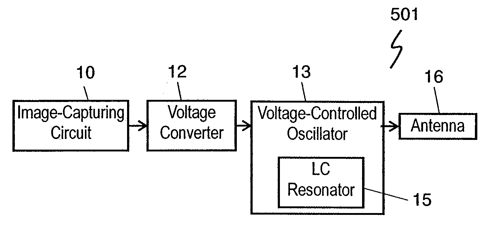
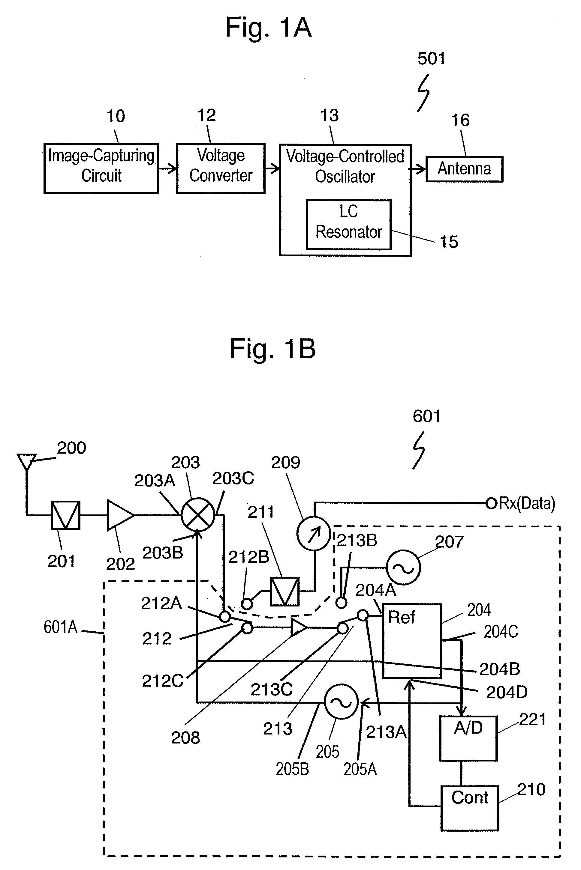
[0059]FIG. 1A is a block diagram of transmitter 501 of a transmission / reception system in accordance with Exemplary Embodiment 1 of the present invention. Image-capturing circuit 10, a transmission data generator, captures an image, and outputs image data, i.e., transmission data, having digital data “0” and “1” as a voltage or a current. Voltage converter 12 converts the image data supplied form image-capturing circuit 10 into a predetermined voltage. Voltage-controlled oscillator 13 generates a high-frequency signal of a frequency determined according to the voltage. The high-frequency signal is frequency-shift-keying-modulated with the image data, and is emitted through antenna 16 as a modulated wave. That is, voltage-controlled oscillator 13 of transmitter 501 generates signals under non-feedback control, while a conventional transmitter shown in FIG. 13 generates signals under feedback control.

[0060]FIG. 4 is a circuit diagram of voltage converter 12 of transmitter 501. Voltag...

exemplary embodiment 2

[0081]FIG. 10 is a block diagram of receiver 602 in accordance with Exemplary Embodiment 2 of the present invention. The same components of receiver 601 of Embodiment 1 shown in FIG. 1B are denoted by the same reference numerals, and their descriptions will be omitted.

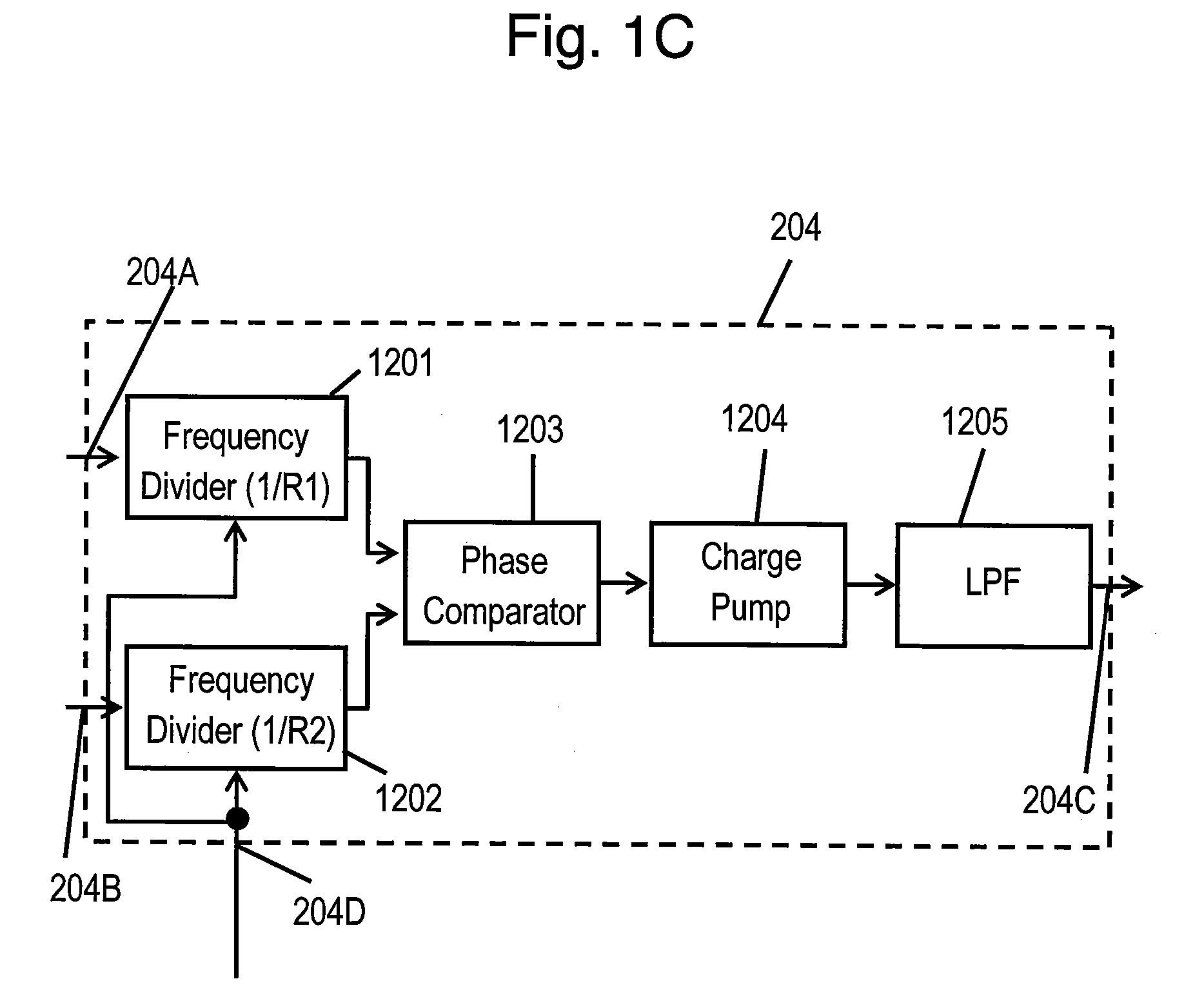
[0082] Receiver 602 includes RSSI detector 215 that detects electric field strength of a signal supplied from band-pass filter 211. A wave received from the antenna is converted into an intermediate-frequency (IF) signal by mixer 203, and supplied to RSSI detector 215. RSSI detector 215 detects the electric field strength of the IF signal and inputs the detected strength to controller 210A. Controller 204A changes control data supplied to phase-locked loop (PLL) circuit 204 as to change an oscillation frequency of voltage-controlled oscillator 205, and determines the data, so that the electric field strength detected by RSSI detector 215 becomes the largest. Voltage-controlled oscillator 205 generates a signal of a fr...

exemplary embodiment 3

[0083]FIG. 11 is a block diagram of receiver 603 in accordance with Exemplary Embodiment 3 of the present invention. The same components of receiver 601 of Embodiment shown in FIG. 1B are denoted by the same reference numerals, and their description will be omitted.

[0084] Receiver 603 includes antenna 200, band-pass filter 201, and low-noise amplifier 202 which are provided for signals of a first frequency band. Receiver 603 further includes antenna 200A, band-pass filter 201A, and low-noise amplifier 202A which are provided for signals in a second frequency band different from the first frequency band. Common port 216A of switch 216 is connected to port 216B for receiving a signal in the first frequency band. Common port 216A of switch 216 is connected to port 216C for receiving a signal in the second frequency band. Controller 210 determines control data to allow voltage-controlled oscillator 205 to generate a signal of a frequency so that mixer 203 supplies IF signals of frequen...


PUM


Abstract

A transmission/reception system includes a transmitter and a receiver. The transmitter includes a voltage converter for generating a voltage according to transmission data, a voltage-controlled oscillator for generating a signal of a frequency corresponding to the voltage generated by the voltage converter under non-feedback control, and a first antenna for emitting the signal generated by the voltage-controlled oscillator. The receiver includes a second antenna for receiving the signal emitted from the first antenna, a first amplifier for amplifying the signal received by the second antenna, an oscillator for generating a local oscillation signal, a mixer for mixing the signal amplified by the first amplifier with the local oscillation signal and converting the signal amplified by the first amplifier into an intermediate-frequency (IF) signal, a detector for detecting the IF signal, and a controller for changing a frequency of the local oscillation signal according to the frequency of the received signal, so that the IF signal has a predetermined frequency.

Description

[0001] This application is a U.S. national phase application of PCT international application PCT / JP2005 / 009420. TECHNICAL FIELD [0002] The present invention relates to a transmission / reception system including a small transmitter and a receiver corresponding to the transmitter for use in an encapsulated endoscope. BACKGROUND ART [0003] An encapsulated endoscope including a transmitter is swallowed for inspection, thus providing less physical burden on a subject and allowing the inspection to be executed regardless of time. Hence, the encapsulated endoscope is used for inspection of small intestines, which can be hardly inspected. [0004] International Patent Application Publication No. WO01 / 65995 discloses a conventional transmission / reception system including a conventional transmitter and receiver. [0005]FIG. 12 is a sectional view of a conventional encapsulated endoscope including conventional transmitter 105. Light emitting diode (LED) 102 illuminates an inside of a human organ,...

Claims


Application Information

Patent Timeline
Patent Type & Authority Applications(United States)
IPC IPC(8): A61B1/00A61B1/04
CPCA61B1/00016A61B1/00036H03J2200/02H03J7/065A61B1/041
Inventor OKADA, EIJIASAKAWA, YASUTERU
Owner PANASONIC CORP
Why Eureka
Try Eureka