Parallel Pulse Signal Processing Apparatus, Pattern Recognition Apparatus, And Image Input Apparatus

a pulse signal and pattern recognition technology, applied in the field of parallel pulse signal processing circuit or neural network, can solve the problems of circuit scale, inability to implement remaining arrangements as electronic circuits, and increase in processing time, so as to reduce circuit scale and power consumption

Active Publication Date: 2007-09-06
CANON KK
View PDF6 Cites 145 Cited by
  • Summary
  • Abstract
  • Description
  • Claims
  • Application Information

AI Technical Summary

Benefits of technology

[0007] The present invention has been made in consideration of the above-described problems, and has as its object to solve the wiring problems and reduce the circuit scale and power consumption.

Problems solved by technology

Of the neural networks according to the prior arts, the arrangement which executes time-sharing multiplexing has a problem that the processing time increases along with an increase in number of synapse connections.
The remaining arrangements can hardly be implemented as an electronic circuit because the increase in circuit scale and the wiring problems become conspicuous as the number of synapse connections increases, and the dynamic range of information (e.g., weight sum value) to be held increases as signals are added through synapse connections.

Method used


Image

  • Parallel Pulse Signal Processing Apparatus, Pattern Recognition Apparatus, And Image Input Apparatus
  • Parallel Pulse Signal Processing Apparatus, Pattern Recognition Apparatus, And Image Input Apparatus
  • Parallel Pulse Signal Processing Apparatus, Pattern Recognition Apparatus, And Image Input Apparatus

Examples


first embodiment

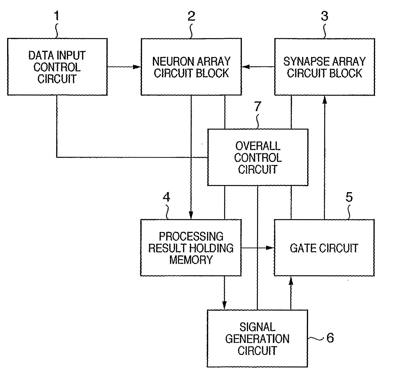
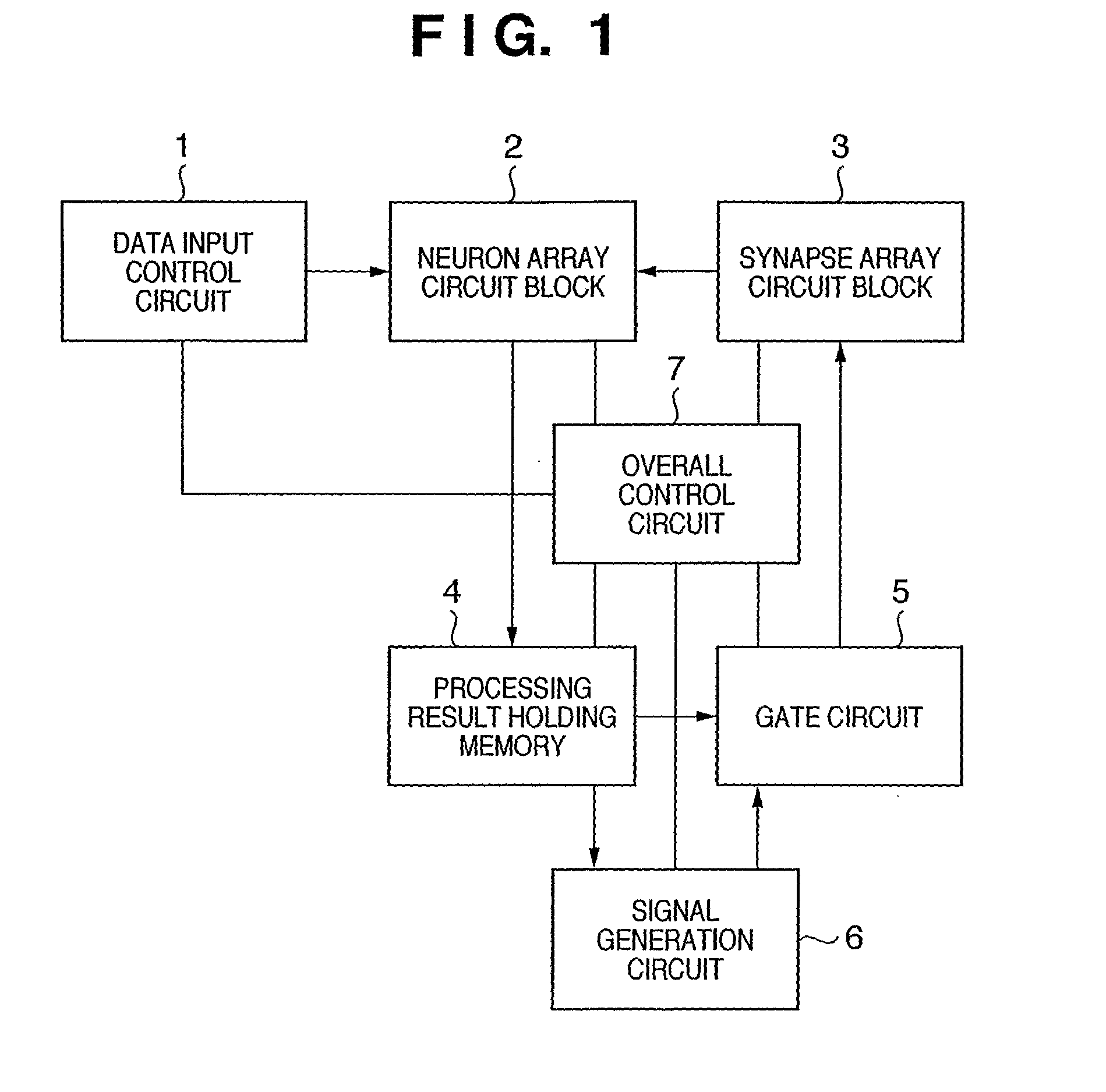
[0097]FIG. 1 shows the arrangement of the main part of a parallel pulse signal processing apparatus. The parallel pulse signal processing apparatus includes, as main constituent elements, a data input control circuit 1, neuron array circuit block 2, synapse array circuit block 3, processing result holding memory 4, gate circuit 5, signal generation circuit 6, and overall control circuit 7.

[0098] Referring to FIG. 1, the data input control circuit 1 is a control circuit to input image data or the like from a sensor or database and incorporates a primary memory. In the neuron array circuit block 2, a plurality of neuron circuits belonging to a predetermined layer in a hierarchical processing structure as shown in FIG. 4 are arrayed. In this embodiment, one layer (or a neuron involved in detecting one feature class in one layer) of a multilayered neural network is implemented in an arbitrary time zone by using the neuron array circuit block 2 and synapse array circuit block 3. A neuro...

second embodiment

[0177] In this embodiment, a pulse signal to a neuron element is input through a common bus line to propagate a bundle of signals after synapse connection. For a feature detection layer neuron, of the outputs from the feature integration layer of the preceding layer, pulses which have undergone phase modulation unique to the feature class are time-serially input. A gate circuit 5 is set after synapse connection circuits on the common bus line where the synapse connections converge.

[0178]FIG. 6 shows the arrangement of the gate circuit used in this embodiment. The gate circuit 5 includes a signal selection unit 50, clock signal input unit 51, gate switch 53, gate control circuit 54, and delay time based comparator 55. The signal selection unit 50 accesses a processing result holding memory 4 to extract a signal from the receptor field. The signal selection unit 50 has no so-called WTA function.

[0179] On the other hand, the comparator 55 is a circuit to select only upper-level signa...

third embodiment

[0197] In this embodiment, on the basis of the distribution of synapse connections which form the receptor field of a feature detection layer neuron, a gate circuit selects a synapse connection whose intensity is maximum and whose absolute value falls within the range of top k (k is a natural number), and passes only a pulse signal from the synapse connection.

[0198]FIG. 5 shows the main part of a parallel pulse signal processing apparatus according to this embodiment. The parallel pulse signal processing apparatus includes, as main constituent elements, a data input control circuit 100, neuron array circuit block 200, synapse array circuit block 300, processing result holding memory 400, gate circuit 500, signal generation circuit 600, and overall control circuit 700. The function of each constituent element is the same as in the first embodiment except the gate circuit 500.

[0199] Unlike the arrangement of the first embodiment, the gate circuit 500 accesses the synapse array circu...


PUM


Abstract

In a parallel pulse signal processing apparatus including a plurality of pulse output arithmetic elements (2), a plurality of connection elements (3) which parallelly connect predetermined arithmetic elements, and a gate circuit (5) which selectively passes pulse signals from the plurality of connection elements, the arithmetic element inputs a plurality of time series pulse signals, executes predetermined modulation processing on the basis of the plurality of time series pulse signals which are input, and outputs a pulse signal on the basis of a result of modulation processing, wherein the gate circuit selectively passes, of the signals from the plurality of connection elements, a finite number of pulse signals corresponding to predetermined upper output levels.

Description

TECHNICAL FIELD [0001] The present invention relates to a parallel pulse signal processing circuit or neural network having a pattern recognition function. BACKGROUND ART [0002] As a scheme for implementing a large-scale neural network by small-scale circuits, an arrangement is conventionally known which executes time-sharing multiplexing by using a conventionally disclosed neuron model to generate a pulse signal (e.g., Japanese Patent Laid-Open No. 5-47870 and Japanese Patent No. 2679730). Another arrangement is also disclosed previously which can solve wiring problems by forming a neuron element by using an element to output a pulse train and a primary storage means (e.g., Japanese Patent Laid-Open No. 6-93249). [0003] In the field of image recognition, a pattern recognition method (method to execute hierarchical template matching) is proposed which implements a recognition processing algorithm specialized to a specific recognition target by using a neural network model whose conc...

Claims


Application Information

Patent Timeline
Patent Type & Authority Applications(United States)
IPC IPC(8): G06F15/18G06N3/063G06K9/46G06N3/04
CPCG06N3/049G06K9/4628G06V10/454
Inventor MATSUGU, MASAKAZU
Owner CANON KK
Why Eureka
Try Eureka