Controller for a power converter and method of operating the same

a power converter and control board technology, applied in the field of power electronics, can solve the problems of increasing losses, limited dynamic response time, and incurring a reduction in power conversion efficiency and physical density produced,

Active Publication Date: 2007-09-13
INTEL CORP
View PDF60 Cites 93 Cited by
  • Summary
  • Abstract
  • Description
  • Claims
  • Application Information

AI Technical Summary

Benefits of technology

[0016] These and other problems are generally solved or circumvented, and technical advantages are generally achieved, by advantageous embodiments of a controller for use with a power converter including a switch configured to conduct to provide a regulated output characteristic at an output of the power converter, and method of operating the same. In one embodiment, the controller includes a linear control circuit, coupled to the output, configured to provide a first control signal for the switch as a function of the output characteristic. The controller also includes a nonlinear control circuit, coupled to the output, configured to provide a second control signal for the switch as a function of the output characteristic. The controller is configured to select one of the first and second control signals for the switch in response to a change in an operating condition of the power converter.

Problems solved by technology

A recognized disadvantage of analog linear controllers is the limited dynamic response time.
The power converters with higher switching frequencies can achieve faster response times and produce lower output ripple voltages, but often incur a reduction in power conversion efficiency and in physical density produced by increased switching losses in the semiconductor devices, by skin effect in various conductors, and by increased losses in magnetic cores of the magnetic devices therein.
Thus, an optimum linear controller designed for a power converter with a switching frequency of 500 kilohertz (“kHz”) cannot achieve a two μs output voltage transition because the control system bandwidth is also 500 kHz, which is not practical with an approach using a linear controller.
However, it is quite difficult to provide control robustness for the power converter because of noise, plant variations, parasitic influences, and non-ideal error amplifiers.
Interleaved power trains generally allow the efficient use of smaller output filter components, particularly output inductors, which are necessary to achieve fast output voltage and current response times. Even if a high switching frequency and interleaved power trains are used, however, sufficient control bandwidth and response times are generally impractical with a linear controller.
A remaining problem, however, is the introduction of significant noise in the control loop as system bandwidth is increased.
Sensing output ripple voltage often worsens output voltage regulation, particularly for step load changes.
The transient response of the control loop for step changes in the output voltage becomes very aggressive since the controller attempts to correct the output voltage error in one switching action, which may be faster than a minimum time.
Conventional controllers are substantially susceptible to noise when expanding a bandwidth of the control loop to a sufficient level to provide fast output voltage control without unnecessary voltage overshoot or control loop stability margins.

Method used


Image

  • Controller for a power converter and method of operating the same
  • Controller for a power converter and method of operating the same
  • Controller for a power converter and method of operating the same

Examples


second embodiment

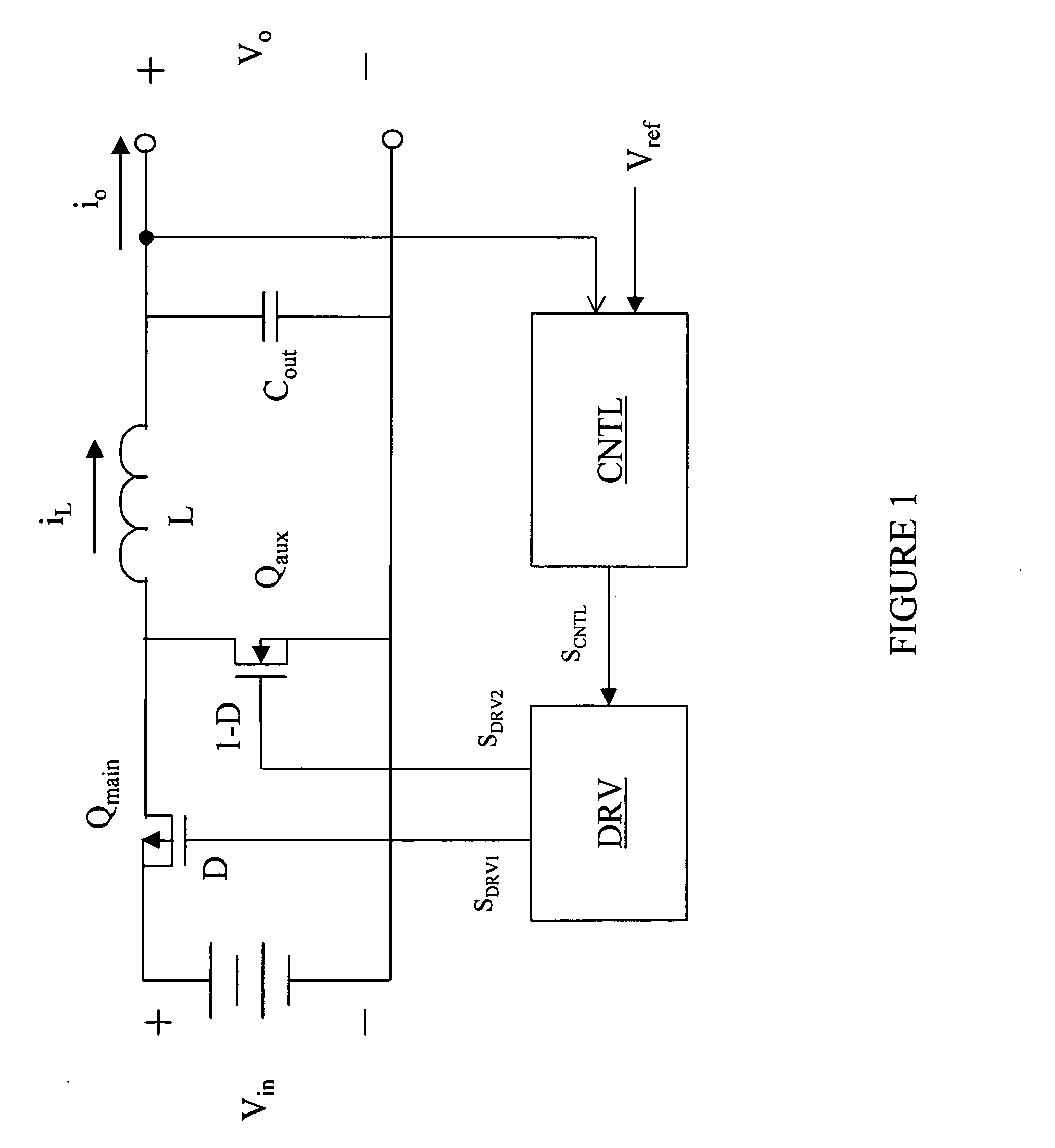
[0036] In a controller feedback of an output capacitor current is used to provide the necessary control loop bandwidth in a high-frequency power converter in a robust way, providing less sensitivity to noise and to circuit parameter uncertainties. In either case, the equivalent linear bandwidth is close to one MHz to meet extreme dynamic response requirements. The exemplary power converters described below follow the guidelines for dynamic voltage scaling and load step regulation as explained by A. Soto, et al. (“Soto”), in “Design Methodology for Dynamic Voltage Scaling in the Buck Converter,” published in the Proceedings of the IEEE Applied Power Electronics Conference, pp. 263-269, 2005, which is incorporated herein by reference.

first embodiment

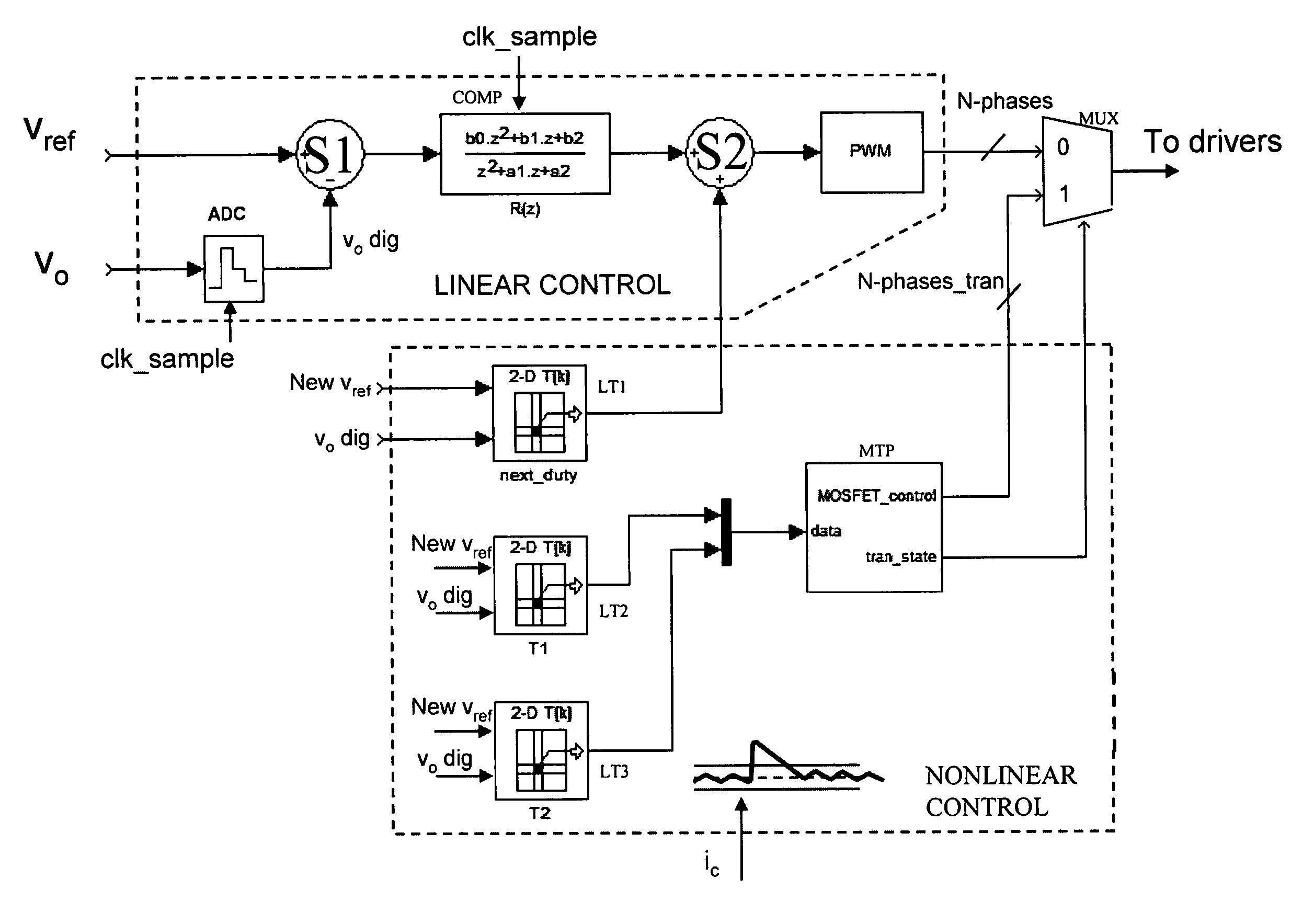
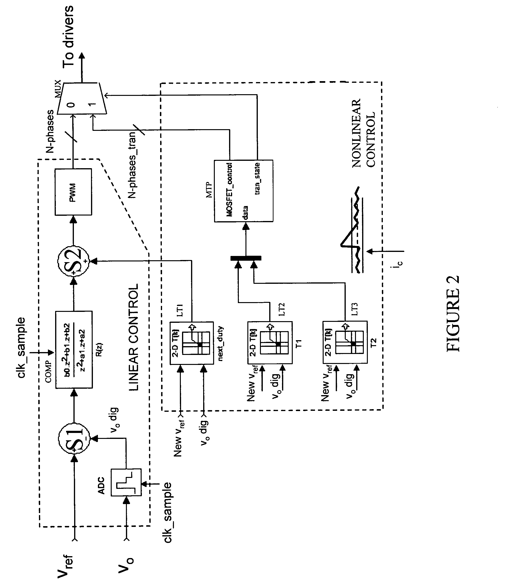
[0037] In the first embodiment mentioned above, a fast action of a substantially ideal nonlinear control circuit is parallel-coupled with a linear control circuit. A difference with prior art implementations is that the linear control circuit is designed substantially at or near the maximum bandwidth that the power converter switching frequency allows, which in a practical design may be roughly one-fifth to one-tenth of the switching frequency. In this way, residual errors remaining after the nonlinear control response are corrected as fast as possible. A significant problem with combining a nonlinear control circuit with a linear control circuit is the control circuit interaction. Digital implementation eases combining the control circuit while allowing substantially maximum bandwidth for the linear control circuit.

[0038] Referring initially to FIG. 1, illustrated is a schematic diagram of an embodiment of a power converter constructed according to the principles of the present inv...


PUM


Abstract

A controller for use with a power converter including a switch configured to conduct to provide a regulated output characteristic at an output of the power converter, and method of operating the same. In one embodiment, the controller includes a linear control circuit, coupled to the output, configured to provide a first control signal for the switch as a function of the output characteristic. The controller also includes a nonlinear control circuit, coupled to the output, configured to provide a second control signal for the switch as a function of the output characteristic. The controller is configured to select one of the first and second control signals for the switch in response to a change in an operating condition of the power converter.

Description

TECHNICAL FIELD [0001] The present invention is directed, in general, to power electronics and, in particular, to a controller for a power converter and method of operating the same. BACKGROUND [0002] A switch mode power converter (also referred to as a “power converter”) is a power supply or power processing circuit that converts an input voltage waveform into a specified output voltage waveform. Controllers associated with power converters manage an operation thereof by controlling the conduction periods of switches employed therein. Generally, controllers are coupled between an input and output of the power converter in a feedback loop configuration (also referred to as a “control loop” or “closed control loop”). [0003] Typically, the controller measures an output characteristic (e.g., an output voltage) of the power converter and based thereon modifies a duty cycle of the switches of the power converter. The duty cycle is a ratio represented by a conduction period of a switch to...

Claims


Application Information

Patent Timeline
Patent Type & Authority Applications(United States)
IPC IPC(8): G05F1/00
CPCH02M3/157H02M3/158H02M2001/0012H02M1/0012
Inventor CERVERA, PEDRO ALOUMARQUEZ, JOSE ANTONIO COBOSLOTFI, ASHRAF W.PECHO, ANDRES SOTO DEL
Owner INTEL CORP
Why Eureka
Try Eureka