
RF power module

a power module and power supply technology, applied in the field of electronic devices, can solve the problems of increasing the size of the mobile communication device as a whole, increasing manufacturing costs, etc., and achieve the effect of enhancing performance and reducing the size of the electronic devi

Active Publication Date: 2007-09-13
MURATA MFG CO LTD
View PDF2 Cites 44 Cited by
  • Summary
  • Abstract
  • Description
  • Claims
  • Application Information

AI Technical Summary

Benefits of technology

[0012]However, providing the antenna switch module between the power amplification module and the antenna may result in an increase in size of the mobile communication device as a whole, leading to an increase in manufacturing cost. For this reason, the antenna switch circuit is proposed to be incorporated into the power amplification module. This can scale down the size of the entire mobile communication device.
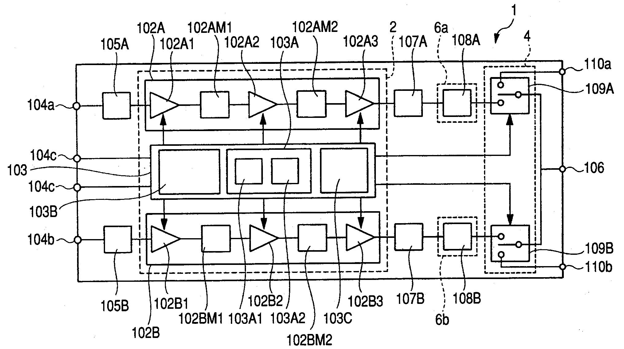
[0015]The high-frequency signal amplified by the power amplifier circuit is input into the antenna switch circuit via the low pass filter circuit. But, when these circuits are incorporated into one power amplification module, without various measures for arrangement of each circuit, the loss of the high-frequency signal may become large from the time when it is amplified by the power amplifier circuit to the time when it is input into the antenna switch circuit via the low pass filter circuit. This could reduce power addition effect of the power amplification module, leading to degraded performance. In particular, when there are provided two systems for GSM 900 and DCS 1800, each including the power amplifier circuit, the low pass filter circuit, and the antenna switch circuit, the power addition effect tends to be reduced depending on the arrangement of each circuit in either the GSM-900 system or the DCS-1800 system.
[0017]Since the power amplification module mounts various components on the wiring board, if the low pass filter circuit and the antenna switch circuit are incorporated into the power amplification module, the number of components mounted will be increased. Thus, if the mounting reliability of various components is not enhanced, the reliability of the power amplification module can be reduced.
[0018]It is therefore an object of the invention to provide a technique that permits reduction in size of an electronic device.
[0019]It is another object of the invention to provide a technique that can enhance the performance of the electronic device.

Problems solved by technology

However, providing the antenna switch module between the power amplification module and the antenna may result in an increase in size of the mobile communication device as a whole, leading to an increase in manufacturing cost.

Method used


Image

  • RF power module
  • RF power module
  • RF power module

Examples


Embodiment Construction

[0061]The following embodiments will be described by being divided into a plurality of sections or embodiments if necessary for convenience. However, unless otherwise specified, they are not irrelevant to one another. One of the embodiments has to do with modifications, details and supplementary explanations of some or all parts of the other. When reference is made to the number of elements or the like (including the number of pieces, numerical values, quantity, range, etc.) in the following description of the embodiments, the number thereof is not limited to a specific number, and may be greater than, or less than, or equal to the specific number, unless otherwise specified and definitely limited to the specific number in principle. It is also needless to say that components (including elements or process steps, etc.) employed in the following description of the embodiments are not always essential, unless otherwise specified and considered to be definitely essential in principle. ...


PUM


Abstract

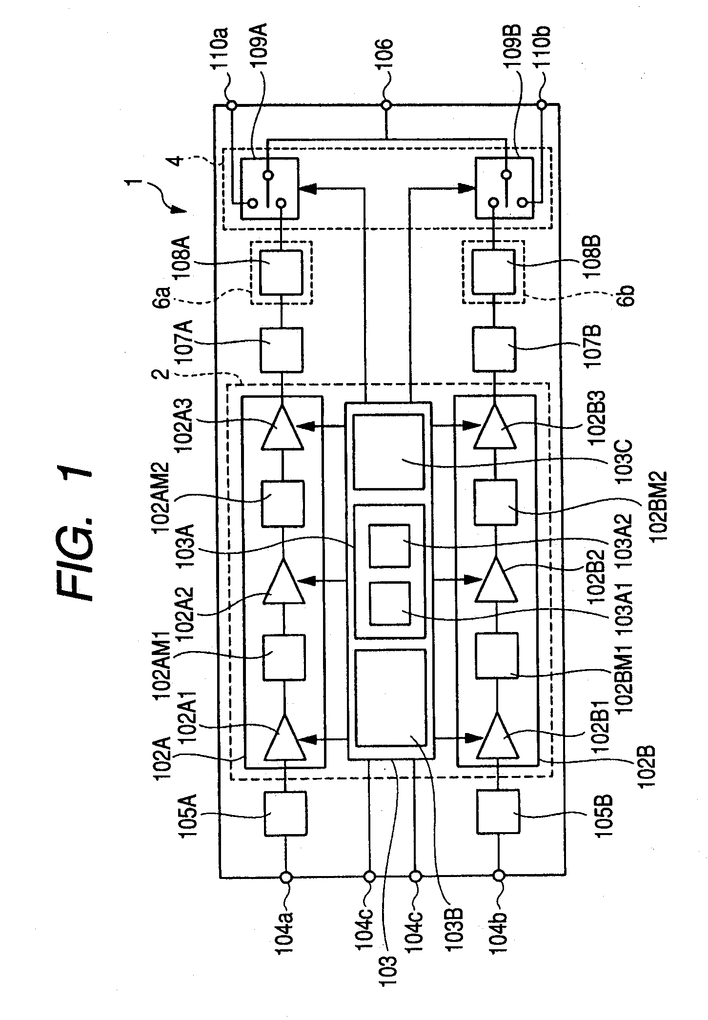
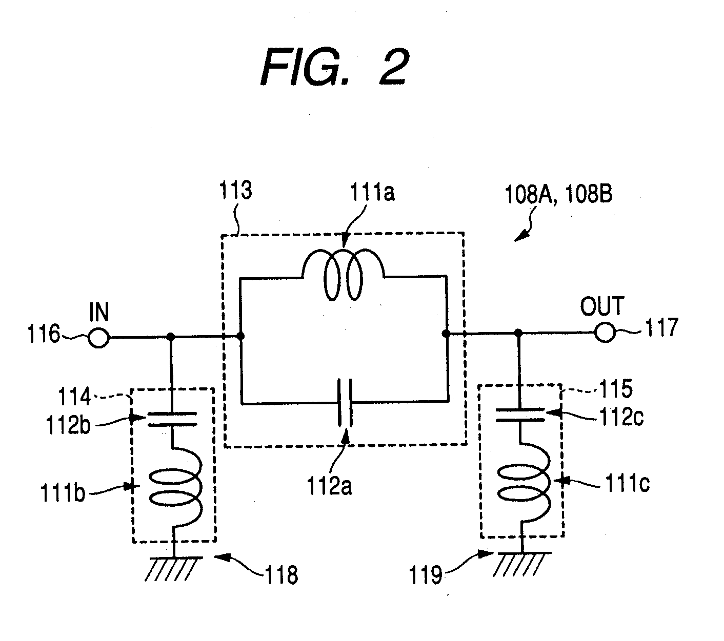
A technique is provided for achieving reduction in size of an electronic device with a power amplifier circuit, while enhancing the performance of the electronic device. An RF power module for a mobile communication device includes first and second semiconductor chips, a passive component, and first and second integrated passive components, which are mounted over a wiring board. In the first semiconductor chip, MISFET elements constituting power amplifier circuits for the GSM 900 and for the DCS 1800 are formed, and a control circuit is also formed. In the first integrated passive component, a low pass filter circuit for the GSM 900 is formed, and in the second integrated passive component, a low pass filter circuit for the DCS 1800 is formed. In the second semiconductor chip, antenna switch circuits for the GSM 900 and DCS 1800 are formed. Over the upper surface of the wiring board, the second semiconductor chip is disposed next to the first semiconductor chip between the integrated passive components.

Description

CROSS-REFERENCE TO RELATED APPLICATION[0001]The present application claims priority from Japanese patent application No. 2006-52099 filed on Feb. 28, 2006, the content of which is hereby incorporated by reference into this application.BACKGROUND OF THE INVENTION[0002]The present invention relates to an electronic device, and more particularly, to a technique suitable for use in an electronic device mounted on a mobile communication device.[0003]In recent years, mobile communication devices (for example, cellular phones), which employ a communication system typified by GSM (Global System for Mobile Communications), PCS (Personal Communication System), PDC (Personal Digital Cellular), or CDMA (Code Division Multiple-Access) system, have gained widespread use throughout the world.[0004]In general, such mobile communication devices are each composed of an antenna for emitting and receiving electric waves, a high-frequency power amplifier (power amplification module) for amplifying power...

Claims


Application Information

Patent Timeline
IPC IPC(8): H03F3/68
CPCH03F3/195H01L2924/3011H03F3/72H03F2200/111H03F2200/294H03F2200/451H01L2224/16225H01L2224/32225H01L2224/48091H01L2224/48227H01L2224/49111H01L2224/49171H01L2224/73265H01L2924/19105H03F3/68H01L2924/30107H01L2924/13091H01L2924/3025H01L2924/1305H01L2924/00014H01L2924/00H01L2924/12032H01L2924/30111H01L2924/181H01L2224/05554H01L2924/00012
Inventor SATO, YUSUKEMAEJIMA, NOBUYOSHIKUDAISHI, TOMOAKIMORIYAMA, SHINJIKURODA, NAOKISATO, RYOTAOKANO, MASASHI
Owner MURATA MFG CO LTD
Learn More