
Method Of Installing An Epoxidation Catalyst In A Reactor, A Method Of Preparing An Epoxidation Catalyst, An Epoxidation Catalyst, A Process For The Preparation Of An Olefin Oxide Or A Chemical Derivable From An Olefin Oxide, And A Reactor Suitable For Such A Process

a technology of epoxidation catalyst and reactor, which is applied in the direction of physical/chemical process catalyst, metal/metal-oxide/metal-hydroxide catalyst, and bulk chemical production, etc. it can solve the problems of providing the combination of reduced capex and/or opex with maintained or reduced plant safety risks, and improve epoxidation processes. , the effect of improving the epoxidation reactor

Inactive Publication Date: 2007-09-13
SHELL OIL CO
View PDF97 Cites 49 Cited by
  • Summary
  • Abstract
  • Description
  • Claims
  • Application Information

AI Technical Summary

Benefits of technology

[0010] The present invention provides such improved epoxidation processes and improved epoxidation reactors. Embodiments of the present invention make use of a reactor which comprises a plurality of microchannels (“process microchannels” hereinafter). The process microchannels may be adapted such that the epoxidation and optionally other processes can take plac

Problems solved by technology

Such apparatus have previously been proposed for use in certain specific fields of application but have not previously been proposed to provide the combination of reduced CAPEX and / or OPEX with maintained or reduced plant safety risks.

Method used


Image

  • Method Of Installing An Epoxidation Catalyst In A Reactor, A Method Of Preparing An Epoxidation Catalyst, An Epoxidation Catalyst, A Process For The Preparation Of An Olefin Oxide Or A Chemical Derivable From An Olefin Oxide, And A Reactor Suitable For Such A Process
  • Method Of Installing An Epoxidation Catalyst In A Reactor, A Method Of Preparing An Epoxidation Catalyst, An Epoxidation Catalyst, A Process For The Preparation Of An Olefin Oxide Or A Chemical Derivable From An Olefin Oxide, And A Reactor Suitable For Such A Process
  • Method Of Installing An Epoxidation Catalyst In A Reactor, A Method Of Preparing An Epoxidation Catalyst, An Epoxidation Catalyst, A Process For The Preparation Of An Olefin Oxide Or A Chemical Derivable From An Olefin Oxide, And A Reactor Suitable For Such A Process

Examples


example 1

[0456] This prophetic example describes how an embodiment of this invention may be practiced.

[0457] In a 400,000 mt / a ethylene oxide plant the stream of recycle gas to the reactor system is 600 mt / h. This flow mainly consists of methane, ethylene, oxygen, argon, carbon dioxide and nitrogen. The temperature at the reactor inlet is 140° C. and the pressure is 2000 kPa gauge.

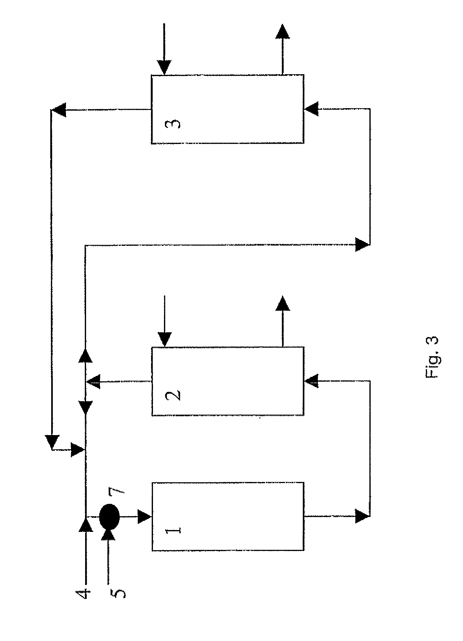
[0458] In FIG. 3, over the catalyst inside the reactor 1, ethylene and oxygen are consumed in the production of ethylene oxide (EO) and carbon dioxide (CO2). After scrubbing the reaction product gases with water to absorb EO in EO absorber 2, and scrubbing part of the recycle gas of CO2 in CO2 absorber 3, feed ethylene, via line 4, and oxygen, via line 5, are supplied to the recycle gas before entering the reactor 1. 37.5 mt / h ethylene is fed to the recycle gas and 34.6 mt / h oxygen. From reactor 1 through absorber 2 and absorber 3 and back to the reactor 1, all of these sections plus the interconnecting pipework ...

example 2

[0460] This prophetic example describes how an embodiment of this invention may be practiced.

[0461] In a 400,000 mt / a ethylene oxide plant the stream of recycle gas to the reactor system is 600 mt / h. This flow mainly consists of methane, ethylene, oxygen, argon, carbon dioxide and nitrogen. The temperature at the reactor inlet is 140° C. and the pressure is 2000 kPa gauge. In FIG. 4, over the catalyst inside the reactor 11, ethylene oxide and carbon dioxide are produced. EO is scrubbed in the EO absorber 12 and part of the recycle gas is scrubbed of CO2 in the CO2 absorber 13. The absorbent used for EO scrubbing is typically water with a small concentration of monoethylene glycol (2-10 weight %). Water saturated with ethylene oxide via line 15 from the bottom of the EO absorber 12 is fed to the top of EO stripper 14. The bottoms flow, line 16, of EO stripper 14 is virtually free of EO and recycled back to the top of EO absorber 13. An ethylene oxide-water mixture (typically contain...

example 3

[0463] This prophetic example describes how an embodiment of this invention may be practiced.

[0464] In a 400,000 mt / a ethylene oxide plant the stream of cycle gas to the reactor system is 600 mt / h. This flow mainly consists of methane, ethylene, oxygen, argon, carbon dioxide and nitrogen. The temperature at the reactor inlet is 140° C. and the pressure is 2000 kPa gauge. In FIG. 5, over the catalyst inside the reactor 31, ethylene oxide and carbon dioxide are produced. EO is scrubbed in the EO absorber 32 and part of the recycle gas is scrubbed of CO2 in the CO2 absorber 33.

[0465] The absorbent used for CO2 scrubbing is typically a cycling activated hot carbonate solution. Absorbent saturated with CO2 from the bottom of the absorber 33 is fed via line 35 to the top of CO2 stripper 34. Here CO2 is vented to atmosphere as a waste gas flow 37. On average this CO2 waste gasflow is 18 mt / h in this example. The bottoms flow 36 of the CO2 stripper 34 is lean in CO2 and cycled back to the...


PUM

PropertyMeasurementUnit
Fractionaaaaaaaaaa
Fractionaaaaaaaaaa
Densityaaaaaaaaaa

Abstract

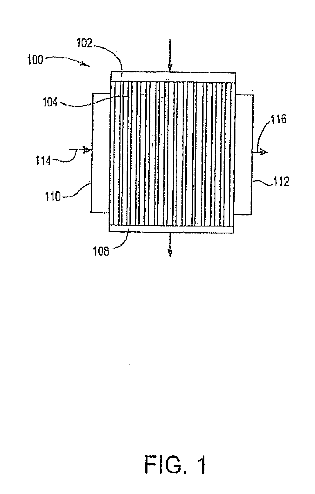
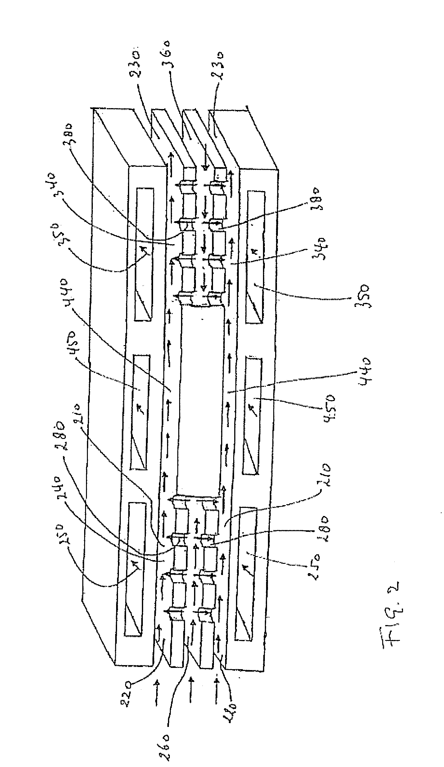
The present invention relates to an improved epoxidation process and an improved epoxidation reactor. The present invention makes use of a reactor which comprises a plurality of microchannels. Such process microchannels may be adapted such that the epoxidation and optionally other processes can take place in the microchannels and that they are in a heat exchange relation with channels adapted to contain a heat exchange fluid. A reactor comprising such process microchannels is referred to as a “microchannel reactor”. The invention also provides a method of installing an epoxidation catalyst in a microchannel reactor. The invention also provides a method of preparing an epoxidation catalyst. The invention also provides an epoxidation catalyst. The invention also provides a certain process for the epoxidation of an olefin and a process for the preparation of a chemical derivable from an olefin oxide. The invention also provides a microchannel reactor.

Description

REFERENCE TO PRIOR APPLICATIONS [0001] This application claims the benefit of U.S. Provisional Application No. 60 / 752,977 filed Dec. 22, 2005.FIELD OF THE INVENTION [0002] The invention relates to a method of installing an epoxidation catalyst in a reactor. [0003] The invention also relates to a method of preparing an epoxidation catalyst. The invention also relates to an epoxidation catalyst. The invention also relates to a process for the epoxidation of an olefin. The invention also relates to a process for the preparation of a chemical derivable from an olefin oxide. In particular, such a chemical may be a 1,2-diol, a 1,2-diol ether, a 1,2-carbonate or an alkanol amine. The invention also relates to a reactor which is suitable for use in such a process. BACKGROUND OF THE INVENTION [0004] Ethylene oxide and other olefin oxides are important industrial chemicals used as a feedstock for making such chemicals as ethylene glycol, propylene glycol, ethylene glycol ethers, ethylene carb...

Claims


Application Information

Patent Timeline
IPC IPC(8): C07D301/03B01J23/58
CPCB01J19/0093B01J23/007C07D301/10B01J23/52B01J23/688B01J23/80B01J35/023B01J37/0215B01J37/0238B01J2219/00783B01J2219/00822B01J2219/00831B01J2219/00833B01J2219/00835B01J2219/0086B01J2219/00873C07C29/106C07C213/04C07D301/03C07D301/08C07C31/202Y02P20/52B01J35/40
Inventor BOLK, JEROEN WILLEMBOS, ALOUISIUS NICOLAAS RENEEEVANS, WAYNE ERROLLOCKEMEYER, JOHN ROBERTMCALLISTER, PAUL MICHAELMARIE RAMAKERS, BERNARDUS FRANCISCUS JOSEFREKERS, DOMINICUS MARIASLAPAK, MATHIAS JOZEF PAUL
Owner SHELL OIL CO
Learn More