Power electronics equipments

a technology of electronics equipment and power electronics, applied in the direction of instruments, baseband system details, process and machine control, etc., can solve the problems of reducing the cost and dimension of the apparatus, adversely affecting the use of a cored transformer as an insulating transformer for signal transmission, and inevitably large circuit scale, etc., to achieve shorten the winding diameter of the primary and secondary windings, shorten the spacing, and facilitate the effect of shortening the winding diameter of the primary and secondary

Active Publication Date: 2007-09-20
FUJI ELECTRIC CO LTD
View PDF15 Cites 42 Cited by
  • Summary
  • Abstract
  • Description
  • Claims
  • Application Information

AI Technical Summary

Benefits of technology

[0046]According to an eighth aspect, the air-cored insulating transformers are manufactured by micro-machining techniques. The manufacture of the air-cored insulating transformers by micro-machining techniques facilitates shortening the winding diameters of the primary and secondary windings and shortening the spacing between the primary and secondary windings. Therefore, the coupling coefficient of the primary and secondary windings is improved, the adverse effects of the external magnetic flux inter...

Problems solved by technology

However, the use of a cored transformer as an insulating transformer for signal transmission is adversely affected by the temperature dependence of the magnetic permeability of a magnetic core material, the high temperature dependence of the coupling coefficient, and the d...

Method used


Image

  • Power electronics equipments
  • Power electronics equipments
  • Power electronics equipments

Examples


first embodiment

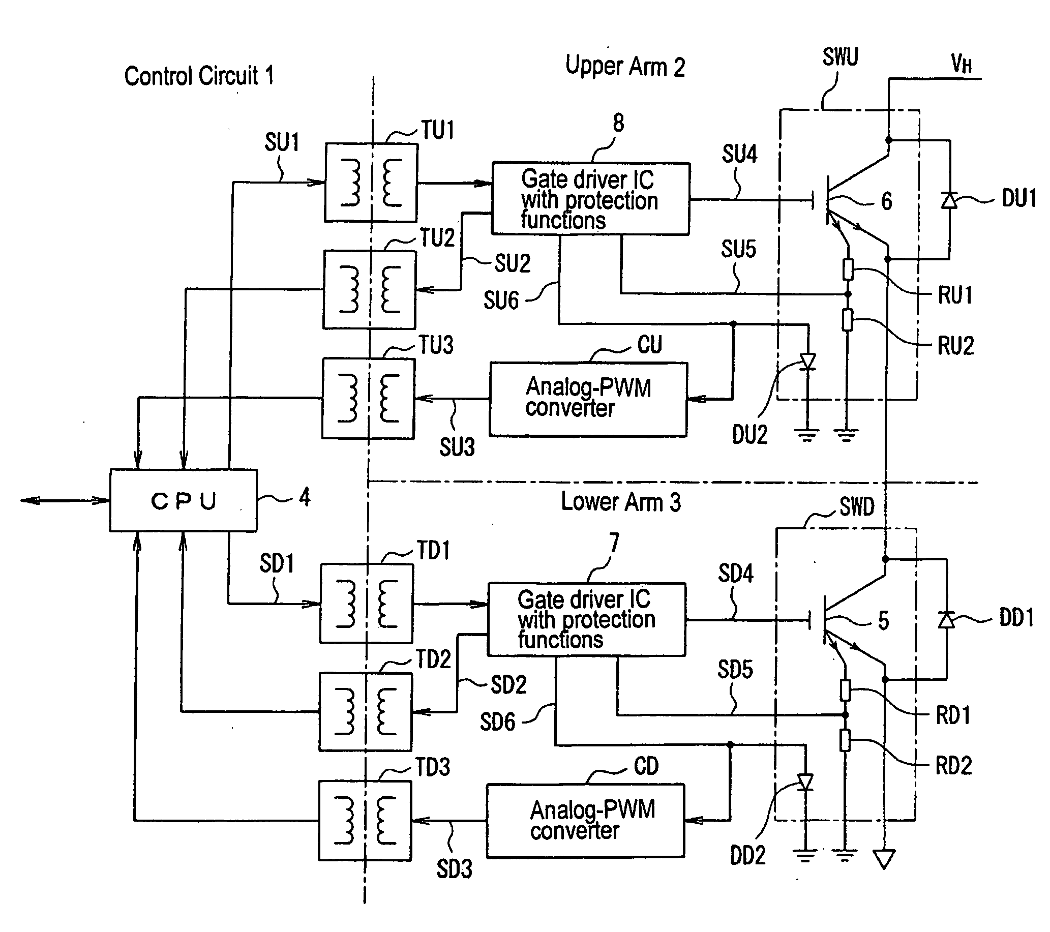
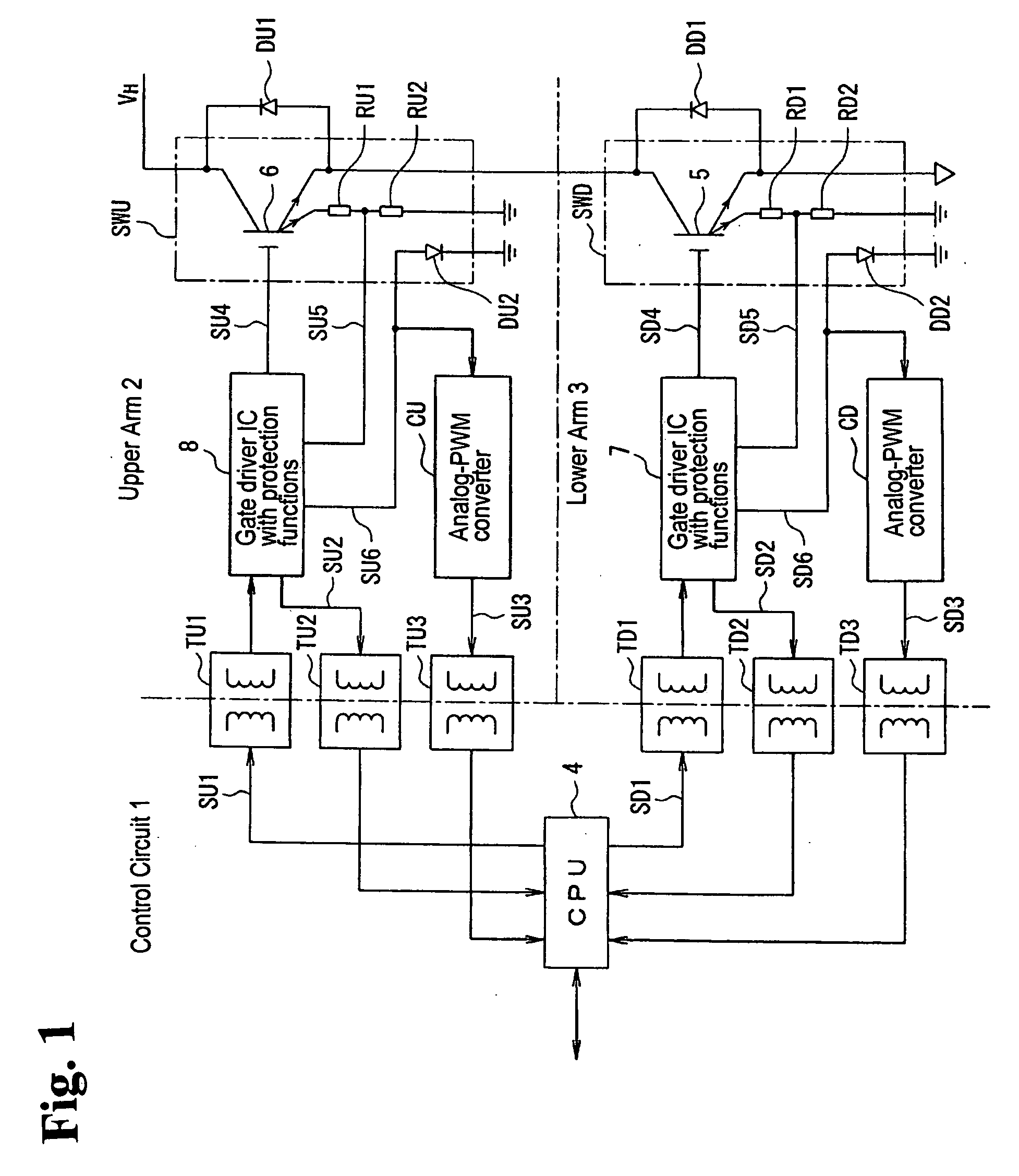
[0066]FIG. 1 is a block diagram schematically showing an intelligent power module (hereinafter referred to as an “IPM”) for a step-up and step-down converter, to which a power electronics equipment according to the invention is applied.

[0067]Referring now to FIG. 1, the IPM for the step-up and step-down converter according to the first embodiment includes a switching device SWU for an upper arm and a switching device SWD for a lower arm that make a current flow to the load and interrupt the current flowing to the load. A control circuit 1 generates control signals directing the conduction and non-conduction of switching devices SWU and SWD. Control circuit 1 may be comprised of a CPU 4 or a logic IC, or a system LSI that mounts a logic IC and a CPU thereon.

[0068]Switching devices SWU and SWD are connected in series so that switching devices SWU and SWD may work for upper arm 2 and for lower arm 3, respectively. An IGBT 6 that conducts switching operations in response to a gate signa...

second embodiment

[0097]FIG. 5(a) is a cross sectional view schematically showing an insulating transformer according to the invention.

[0098]FIG. 5(b) is a top plan view of the insulating transformer shown in FIG. 5(a).

[0099]Referring now to FIGS. 5(a) and 5(b), a lead wiring layer 12 is buried in a substrate 11 and a primary coil pattern 14 is formed on substrate 11. Primary coil pattern 14 is connected to lead wiring layer 12 via a leading port 13. A flattening film 15 is formed on primary coil pattern 14. A secondary coil pattern 17 is formed above flattening film 15 with an insulator film 16 interposed between flattening film 15 and secondary coil pattern 17. Secondary coil pattern 17 is covered with a protector film 18.

[0100]A lead wiring layer 22 is buried in a substrate 21 and a secondary coil pattern 24 is formed on substrate 21. Secondary coil pattern 24 is connected to lead wiring layer 22 via a leading port 23. Secondary coil pattern 24 is covered with a protector film 25.

[0101]Primary coi...

third embodiment

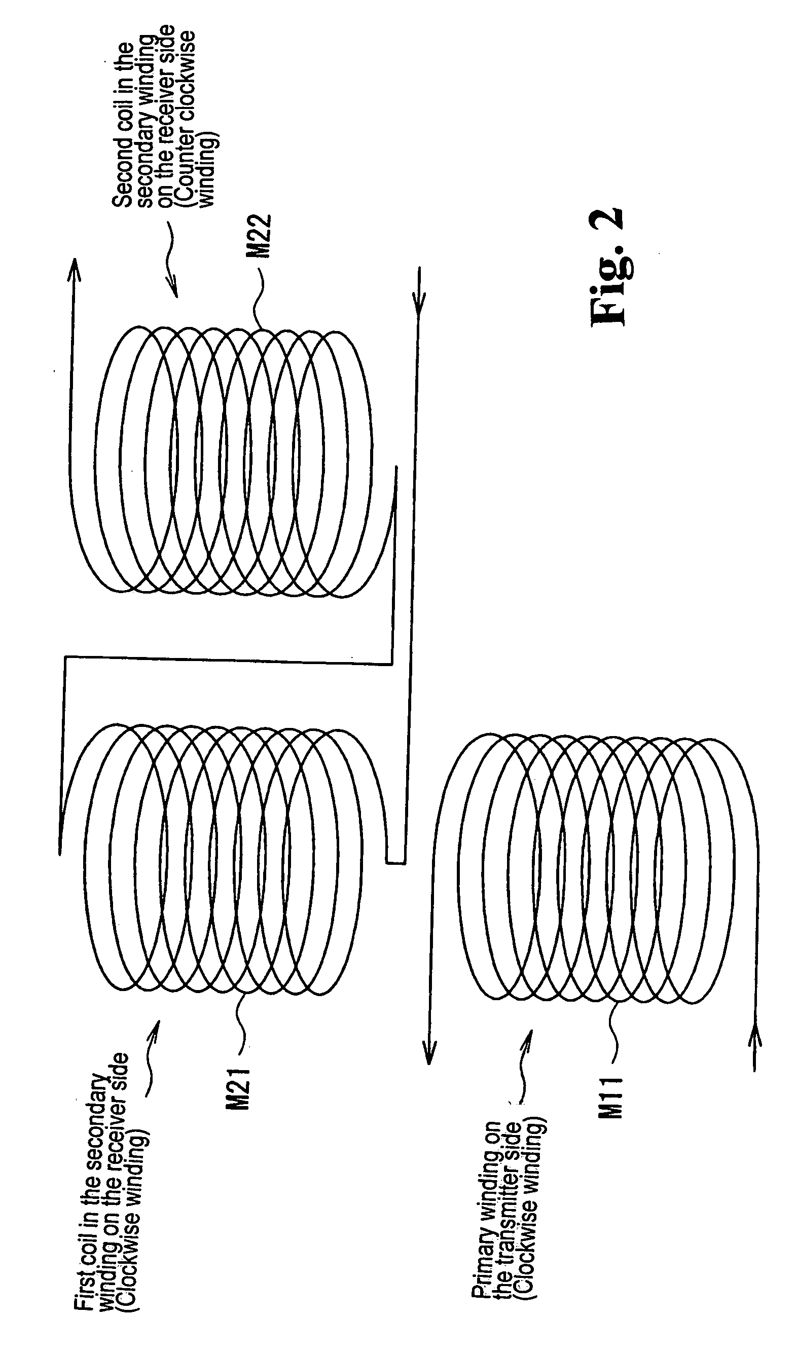
[0104]FIG. 6 schematically shows the external appearance of an air-cored insulating transformer according to the invention.

[0105]Referring now to FIG. 6, each of air-cored insulating transformers TU1 through TU3 and TD1 through TD3 shown in FIG. 1 includes a primary winding, working as a transmitter, and a first primary coil M111. A second primary coil M112 and a secondary winding working as a receiver include a first secondary coil M121 and a second secondary coil M122. First primary coil M111 and second primary coil M112 may be configured such that the signal magnetic flux intersecting the secondary winding is intensified. In addition, first secondary coil M121 and second secondary coil M122 may be configured such that the voltages caused by the external magnetic flux intersecting the secondary winding cancel each other and the voltage generated by the signal magnetic flux intersecting the secondary winding is intensified.

[0106]For example, the winding direction of first primary c...


PUM


Abstract

Power electronics equipment includes a switching device directing current flow to a load and interrupting the current flowing to the load, a control circuit generating a control signal directing the conduction and non-conduction of the switching device, a driver circuit driving a control terminal of the switching device based on the control signal, and at least one air-cored insulating transformer insulating the control circuit and the driver circuit from each other. Each air-cored insulating transformer includes a primary winding and a secondary winding configured to generate a voltage by a change of interlinkage of a magnetic field. The secondary winding includes a plurality of coils configured such that voltages generated by external magnetic flux intersecting the secondary winding are canceled and a voltage generated by the signal magnetic flux intersecting the secondary winding is increased.

Description

BACKGROUND OF THE INVENTION AND RELATED ART STATEMENT[0001]The present invention relates to power electronics equipment. Specifically, the present invention relates to power electronics equipment well suited for transmitting signals to switching devices via air-cored insulating transformers.[0002]On-vehicle equipment mounts a step-up and step-down converter and an inverter on the driving system of a motor that generates driving power for improving conversion efficiency and for reducing the energy consumption.[0003]FIG. 11 is a block diagram schematically showing a vehicle driving system that employs a conventional step-up and step-down converter.[0004]Referring now to FIG. 11, the vehicle driving system includes a power supply 101 that feeds electric power to a step-up and step-down converter 102 that boosts and steps down a voltage, an inverter 103 that converts the voltage outputted from step-up and step-down converter 102 to the components of a three-phase voltage, and a motor 10...

Claims


Application Information

Patent Timeline
IPC IPC(8): G05F1/325
CPCH04L25/0266H01L2224/48137H01L2924/1305H01L2924/13055H01L2924/00H01L2924/00014H01L2224/45099
Inventor YOSHIMURA, HIROYUKI
Owner FUJI ELECTRIC CO LTD
Why Eureka
Try Eureka