DC current regulator insensitive to conducted EMI

a current regulator and conductor technology, applied in the direction of electric variable regulation, instruments, electrical apparatus, etc., can solve the problem of being much more prone to noise conducting interference, and achieve the effect of smooth outpu

Active Publication Date: 2007-09-20
AMI SEMICON BELGIUM
View PDF7 Cites 11 Cited by
  • Summary
  • Abstract
  • Description
  • Claims
  • Application Information

AI Technical Summary

Benefits of technology

[0010] In this manner, a feedback loop is provided from the first circuit node, the second amplifier input, the output of the amplifier, the input of the transistor, the second leg of the transistor and via the current mirror back to the first circuit node. The loop is subject to the effects of the low-pass filter. The low-pass filter has an advantage of shielding the amplifier and other parts of the circuit from EMI. Isolating the first leg (i.e. the source) of the transistor from the first circuit node, by use of the current mirror, prevents EMI from clipping, and thus distorting, the output current, as occurs in conventional regulators. A further advantage of the improved regulator is that the external EMI source connected to the first circuit node “sees” a high impedance drain (e.g. of an MOS transistor M3 in FIG. 7) instead of a low impedance source, e.g. of an MOS transistor such as M1 in FIG. 1. This also increases the effectiveness of any decoupling capacitor which is connected between the first circuit node and ground. A further advantage is that Ci of the filter can be small, due to the Miller effect of the filter. This makes it advantageous when the circuit is implemented in an integrated circuit, where it is desirable to keep the capacitance as low as possible. A still further advantage is that EMI disturbance is filtered before it reaches the input of the amplifier. A DC shift at the output of the amplifier due to EMI injection at its input is avoided because the signal at the input to the opamp is already filtered by the filter.
[0012] This provides the advantage that the output is smoothed still further with respect to EMI frequencies.

Problems solved by technology

Due to their small size, microelectronic circuits are in practice not easily disturbed by radiated disturbances, they are however much more prone to noise conducting interferences, that are present on PCB tracks.
Current mirrors and current regulators are two commonly used elements in analog circuitry which can be susceptible to conducted EMI.

Method used


Image

  • DC current regulator insensitive to conducted EMI
  • DC current regulator insensitive to conducted EMI
  • DC current regulator insensitive to conducted EMI

Examples


Embodiment Construction

[0042] The present invention will be described with respect to particular embodiments and with reference to certain drawings but the invention is not limited thereto but only by the claims. The drawings described are only schematic and are non-limiting. In the drawings, the size of some of the elements may be exaggerated and not drawn on scale for illustrative purposes. Where the term “comprising” is used in the present description and claims, it does not exclude other elements or steps. Furthermore, the terms first, second, third and the like in the description and in the claims, are used for distinguishing between similar elements and not necessarily for describing a sequential or chronological order. It is to be understood that the terms so used are interchangeable under appropriate circumstances and that the embodiments of the invention described herein are capable of operation in other sequences than described or illustrated herein.

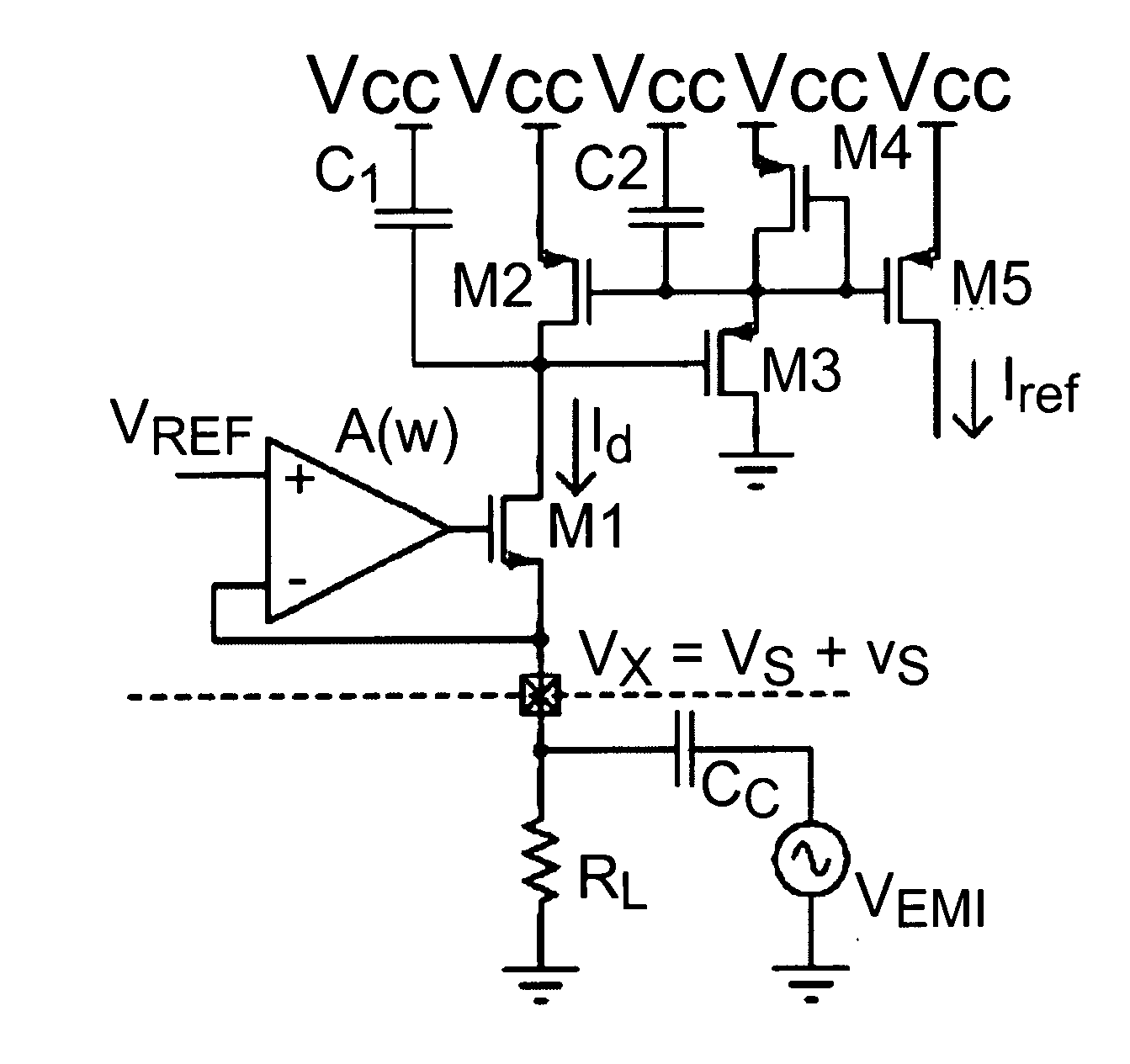
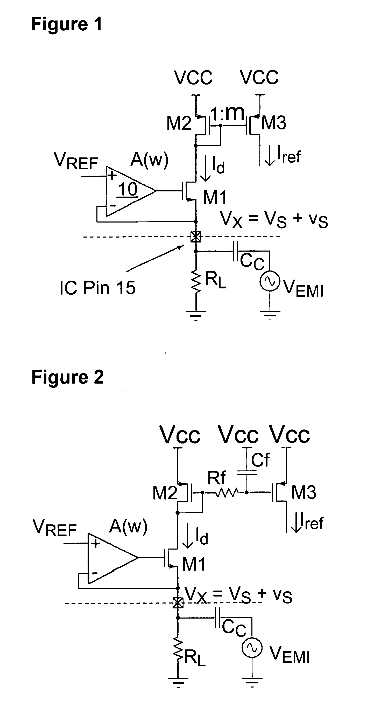
[0043]FIG. 1 shows a current regulator which ...


PUM


Abstract

A DC current regulator circuit comprises a first circuit node (32) which is operable to receive an external input voltage. A transistor (M1) has an input, a first leg and a second leg. The first leg of the transistor is isolated from the first circuit node (32). An amplifier (10) has an output connected to the input of the transistor (M1), a first amplifier input for receiving a reference voltage (VREF) and a second amplifier input connected to the first circuit node (32). A low-pass filter (33) connects between the output of the amplifier and the first circuit node (32). A current mirror (36) connects in series with the second leg of the transistor (M1) and has a first branch (38) for providing a regulated output current and a second branch (37) which connects to the first circuit node (32). The current regulator has reduced sensitivity to conducted EMI received at the first circuit node (32).

Description

FIELD OF THE INVENTION [0001] This invention relates to DC current regulators and to current mirrors and to methods of operating the same. BACKGROUND TO THE INVENTION [0002] The phenomenon of electromagnetic interference (EMI) and the resulting general framework defining to what extent electronic devices and applications must be able to work together without disturbing each other (electromagnetic compatibility, abbreviated EMC) first became a concern during the second World War. One of the top EMI nuisances at that time was the electric motor noise, conducted through power supply lines into sensitive electronic equipment. Since then, the major increase of electronic appliances, the use of higher frequencies and the omnipresence of (fast) switching digital computing devices have made EMC a global concern, that has gained much importance over the years. With appliances working at speeds of a few hundred megahertz, to some gigahertz, even the tiniest track of the most carefully designe...

Claims


Application Information

Patent Timeline
IPC IPC(8): H03F3/45
CPCG05F3/262G05F1/56
Inventor REDOUTE, JEAN-MICHEL VLADIMIRSTEYAERT, MICHIEL
Owner AMI SEMICON BELGIUM
Why Eureka
Try Eureka