
Tri-phase surge protector and its manufacturing method

a technology of surge protector and manufacturing method, which is applied in the direction of overvoltage protection resistor, emergency protection arrangement for limiting excess voltage/current, and arrangements responsive to excess voltage, etc., can solve the problems of surge protector being deteriorated seriously, surge protector will operate abnormally, and several surge protectors connected in parallel will lose the original intended function. , to achieve the effect of improving product life and reliability

Active Publication Date: 2007-09-20
POWERTECH INDAL
View PDF3 Cites 6 Cited by
  • Summary
  • Abstract
  • Description
  • Claims
  • Application Information

AI Technical Summary

Benefits of technology

[0009] The primary objective of the present invention is to provide a tri-phase surge protector and its manufacturing method design a three-wire L-N-G protection on a zinc oxide ceramic body to improve product life and reliability.
[0010] The secondary objective of the present invention is to provide a tri-phase surge protector and its manufacturing method that can achieve the effect of connecting two, three, or more surge protectors in parallel by appropriately adjusting the area, and also can overcome the surge attack and an incapability of starting if different surge protectors (corresponding to different breakdown voltages) are connected in series between two same lines. If different surge protectors are started successively, the low-impedance surge protector will bear a larger current (for the connection in parallel) since the remained impedance of each surge protector is different. After the use of a long time, the surge protector will be deteriorated seriously. If any one of the surge protectors fails, then several surge protectors connected in parallel will lose its original intended function.
[0011] The third objective of the present invention is to solve the failure problem of the prior art surge protector that requires an overheat protecting device for each surge protector, so as to save the overheat protecting device and lower its cost while maintaining a reasonable protection function.
[0012] The fourth objective of the present invention is to provide a better heat dissipating solution. Since the method of eliminating external energies of the surge protector produces joule heat, the temperature will rise if the heat dissipating rate is lower than the speed of producing heat. As a result, the surge protector will operate abnormally and the surge protector will be burned. Although the surge working area between any two lines is very close to the area of a single surge protector, the total volume is three times of the original single surge protector. For the same surge energy, the temperature rise of the tri-phase surge protector of the invention is smaller. Since the overall area is larger, the heat dissipating rate of the tri-phase surge protector can be increased greatly. Therefore, a better protection is provided for intensive continuous surge attacks to improve product life and reliability.
[0015] To make it easier for our examiner to understand the objective of the invention, its structure, innovative features, and performance, we use a preferred embodiment together with the attached drawings for the detailed description of the invention.

Problems solved by technology

After the use of a long time, the surge protector will be deteriorated seriously.
If any one of the surge protectors fails, then several surge protectors connected in parallel will lose its original intended function.
As a result, the surge protector will operate abnormally and the surge protector will be burned.

Method used


Image

  • Tri-phase surge protector and its manufacturing method
  • Tri-phase surge protector and its manufacturing method
  • Tri-phase surge protector and its manufacturing method

Examples


Embodiment Construction

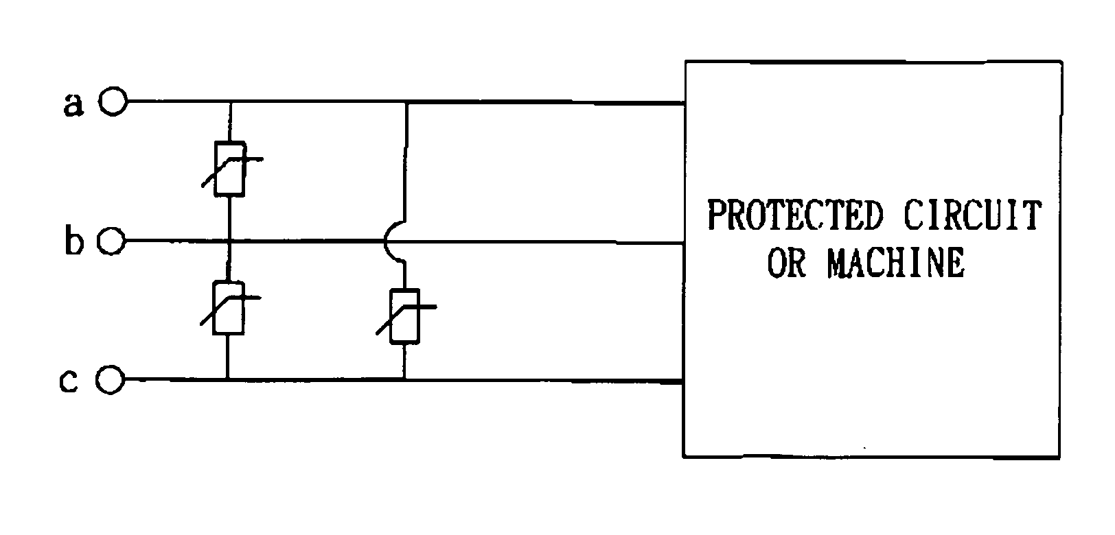
[0026] Referring to FIGS. 5(a) and 5(b) respectively for the cross-sectional view and the schematic equivalent circuit diagram of a tri-phase surge protector according to a preferred embodiment of the present invention, the tri-phase surge protector comprises a first zinc oxide ceramic body 10, a first electrode layer 20, a second electrode layer 30, a second zinc oxide ceramic body 40, a third electrode layer 50, a third zinc oxide ceramic body 60, and a fourth electrode layer.

[0027] The first zinc oxide ceramic body 10 has the same functions as a zinc oxide ceramic body 6 of a prior art surge protector for providing a breakdown path for the surge protector, and the first electrode layer 20 is disposed on a surface of the first zinc oxide ceramic body 10 and having a first electrode 21, and the first electrode 21 includes a first terminal a, wherein the first terminal a is but not limited to a grounding terminal (Ground).

[0028] The second electrode layer 30 is disposed on another...


PUM

PropertyMeasurementUnit
voltageaaaaaaaaaa
areaaaaaaaaaaa
conductiveaaaaaaaaaa

Abstract

A tri-phase surge protector comprises a first zinc oxide ceramic body; a first electrode layer on a surface of the first zinc oxide ceramic body and having a first electrode, and the first electrode includes a first terminal; a second electrode layer on another surface of the first zinc oxide ceramic body; a second zinc oxide ceramic body on the second electrode layer; a third electrode layer on another surface of the second zinc oxide ceramic body and having a second electrode, and the second electrode includes a second terminal; a third zinc oxide ceramic body on the second electrode layer and at the second zinc oxide ceramic body; and a fourth electrode layer on another surface of the third zinc oxide ceramic body and having a third electrode, and the third electrode includes a third terminal. The invention also discloses a method for manufacturing a tri-phase surge protector.

Description

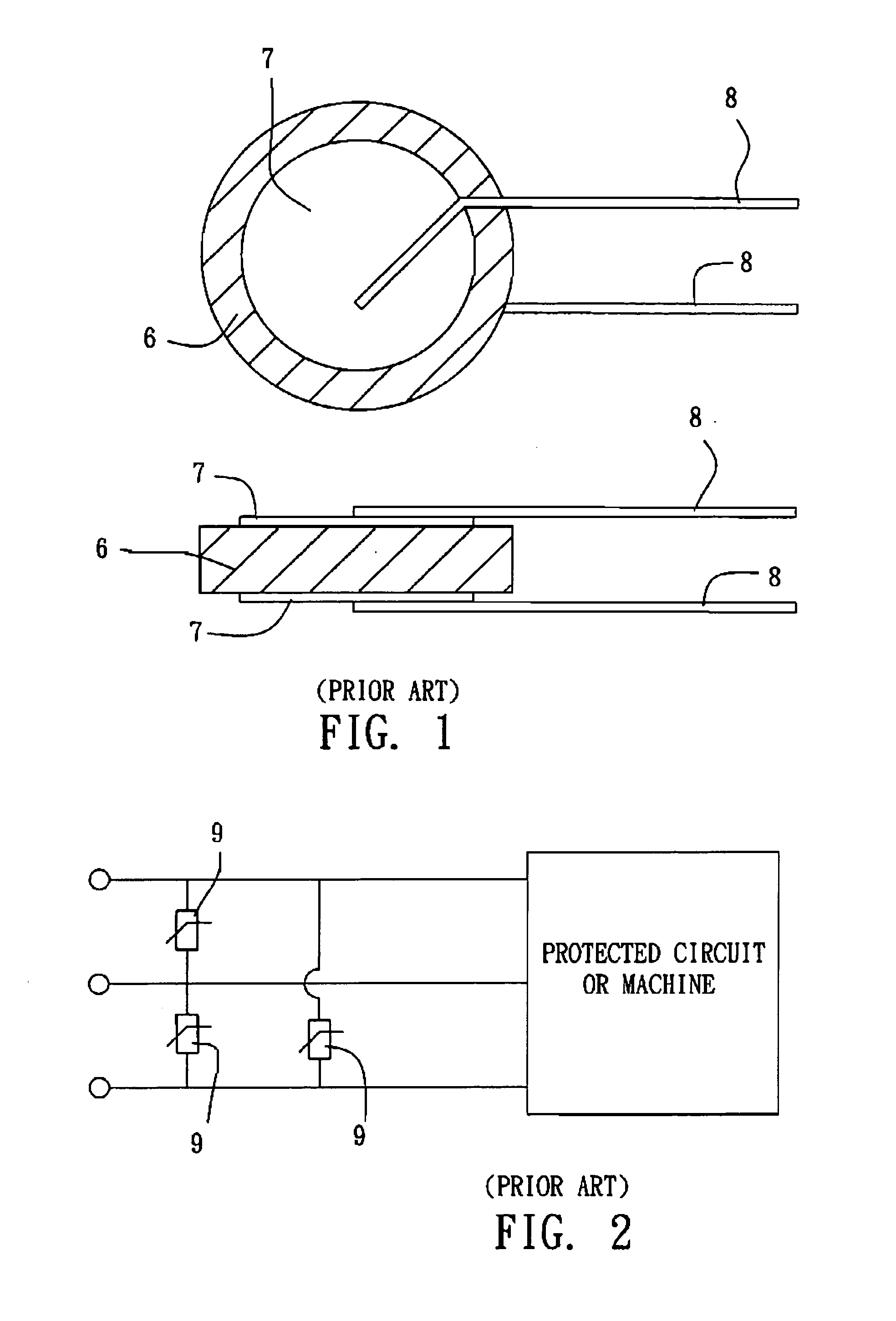
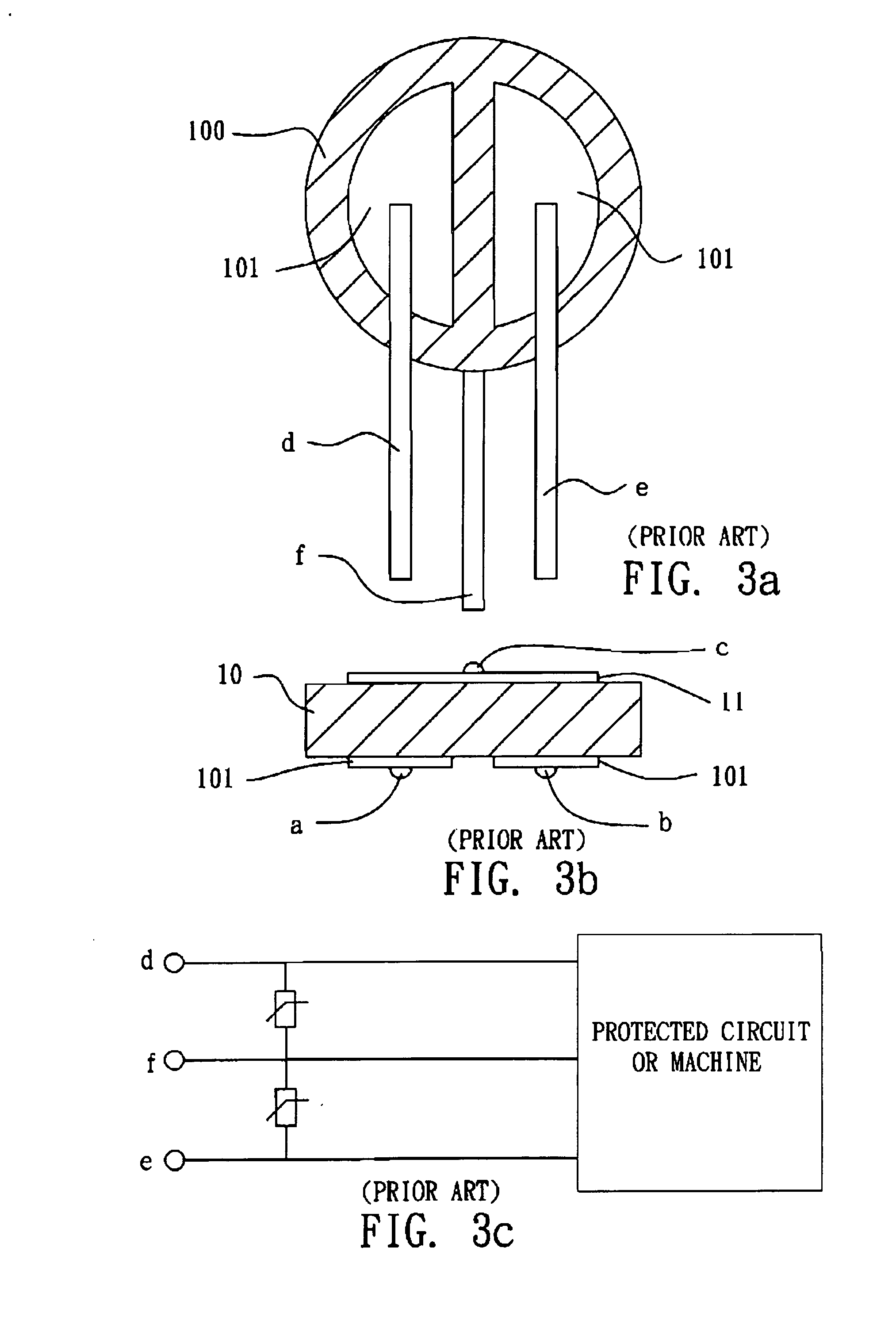
BACKGROUND OF THE INVENTION [0001] 1. Field of the Invention [0002] The present invention relates to a tri-phase surge protector and its manufacturing method, and more particularly to a tri-phase surge protector and its manufacturing method that design a three-wire L-N-G protection on a zinc oxide ceramic body to improve the life and reliability. [0003] 2. Description of the Related Art [0004] Referring to FIG. 1 for a bottom view and a side view of a prior art surge protector, the prior art surge protector includes a zinc oxide ceramic plate 6 having a conductive layer 7a on both top and bottom sides of the zinc oxide ceramic plates, a copper wire 8 (usually a tin plated copper wire) soldered on an electrode surface 7, an epoxy resin powder coated on an external layer for insulating electric charges and resisting moisture. The operating principle of the prior art surge protector uses a grain boundary phenomenon of the zinc oxide ceramic plate 6 to protect a voltage surge occurred a...

Claims


Application Information

Patent Timeline
Patent Type & Authority Applications(United States)
IPC IPC(8): H02H9/06
CPCH02H9/042
Inventor LU, YUNG-HAO
Owner POWERTECH INDAL
Learn More