
Apparatus and methods for interlocking stent segments

a luminal prosthesis and appendix technology, applied in the field of medical devices and methods, can solve the problems of insufficient selection of stents, inability to accurately assess, increased cost and longer procedure time, etc., and achieve the effect of maintaining flexibility

Inactive Publication Date: 2007-09-20
XTENT INC
View PDF1 Cites 122 Cited by
  • Summary
  • Abstract
  • Description
  • Claims
  • Application Information

AI Technical Summary

Benefits of technology

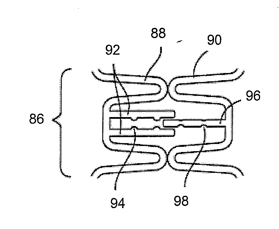
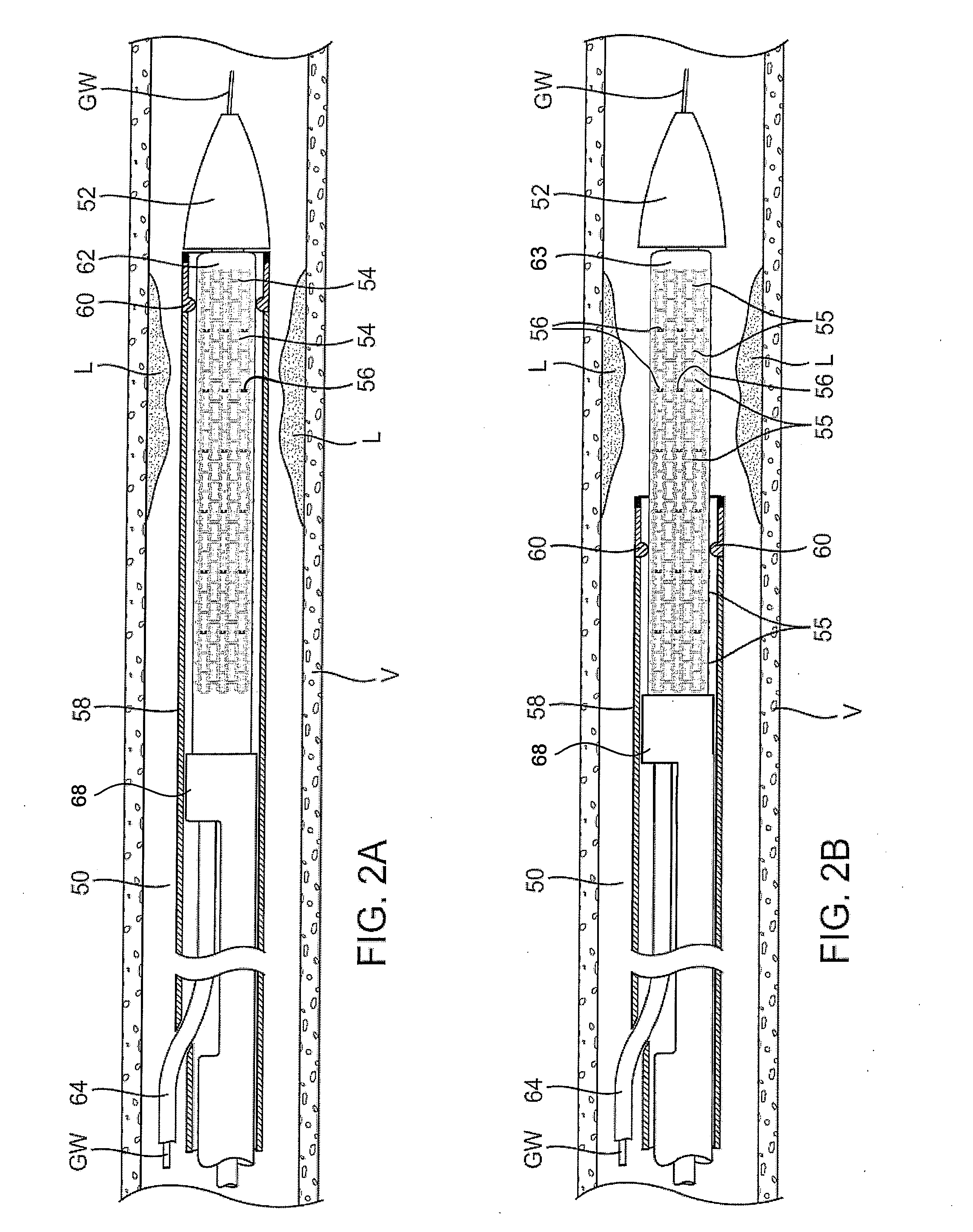
[0012]As described, customized, variable length, luminal medical prosthesis can be delivered effectively to one or more treatment sites in irregularly shaped or highly tapered coronary arteries or other vessels, using a single delivery device, during a single interventional procedure. Because the length of the deployed stent is variable depending upon the length of the lesion to be treated, the number of stent segments deployed into a vessel may be altered in situ. Additionally, one or more disconnected stent segments enable a delivery catheter to maintain its flexibility, particularly when the delivery catheter is advanced through tortuous intravascular pathways. Thus, ease of release and deployment of stent segments adjacent to one another is desirable.
[0013]However, it is desirable to maintain a relatively secure engagement between the expanded stent segments and the vessel wall, particularly along tapered vessels or vessels with an uneven anatomy, while also minimizing or preventing migration of an expanded stent segment relative to the other expanded stent segments. Stent segments which are able to slide freely relative to one another along the deployment catheter prior to expansion may be secured to one another when expanded and / or deployed into the vessel. Securement upon expansion of the stent segments may be accomplished, in part, by utilizing one or more coupling mechanisms between adjacent stent segments which securely interlock the segments to one another by taking advantage of the changing geometry of the stents during expansion.
[0014]One method for delivering a luminal prosthesis to at least one treatment site comprises providing a plurality of radially expandable prosthetic stent segments arranged axially along a delivery catheter with at least some of the adjacent prosthetic stent segments being disconnected from one another and having one or more coupling structures between the prosthetic stent segments. The delivery catheter may be positioned at a first treatment site and two or more prosthetic stent segments are selected for deployment. The selected segments are radially expanded without expanding the segments remaining on the delivery catheter and one or more coupling mechanisms between the expanded stent segments may permit the selected stent segments to become secured to one another in their expanded state.

Problems solved by technology

Restenosis, where treated vessels such as coronary arteries tend to become re-occluded following stent implantation, was a problem in early stent technology.
Sometimes, however, lesion length cannot be assessed accurately and can result in the selection of stents which are not long enough to adequately cover the target lesion.
The use of multiple delivery catheters results in greater cost and longer procedure time.
In addition, and particularly in peripheral stenting, overlapping of stents can be problematic.
In situations where vessels are tapered or have other irregularities in diameter, e.g., around the ostia of a vessel, a single balloon of constant diameter may have difficulty in expanding all of the stent segments to engage tightly with the vessel wall.

Method used


Image

  • Apparatus and methods for interlocking stent segments
  • Apparatus and methods for interlocking stent segments
  • Apparatus and methods for interlocking stent segments

Examples


Embodiment Construction

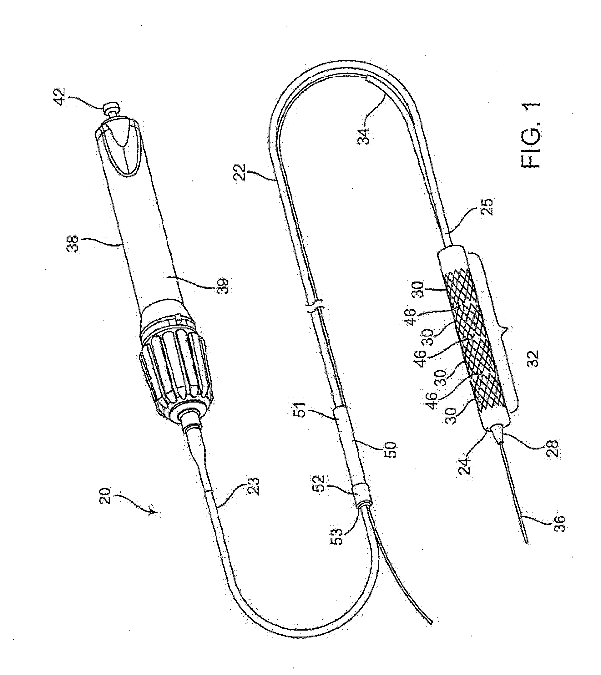
[0053]An example of a luminal prosthesis delivery system 20 which may be utilized with the one or more stent segments described herein is illustrated in the perspective assembly view of FIG. 1. Luminal prosthesis delivery system 20 generally comprises a catheter shaft 22 with an outer sheath 25 slidably disposed over an inner shaft (not shown). An inflatable balloon 24 is mounted on the inner shaft and is exposed by retracting sheath 25 relative to the inner shaft. A tapered nosecone 28, composed of a soft elastomeric material to reduce trauma to the vessel during advancement of the delivery system is attached distally of the inflatable balloon 24. A luminal prosthesis 32 comprises a plurality of separable stent segments 30 mounted over the inflatable balloon 24 for expansion. A guidewire tube 34 is slidably positioned through sheath 25 proximal to the inflatable balloon 24. A guidewire 36 is positioned slidably through guidewire tube 34, inflatable balloon 24 and nosecone 28 and ex...


PUM


Abstract

Apparatus and methods for interlocking stent segments which provide for a secure engagement between the expanded stent segments are described herein. Stent segments which are able to slide freely relative to one another along the deployment catheter prior to expansion may be secured to one another when expanded and / or deployed into the vessel. Securement upon expansion of the stent segments may be accomplished, in part, by utilizing one or more coupling mechanisms between adjacent stent segments which securely interlock the segments to one another by taking advantage of the changing geometry of the stents during expansion.

Description

CROSS-REFERENCE TO RELATED APPLICATIONS[0001]This application claims the benefit of priority to U.S. Provisional Patent Application No. 60 / 784,309 filed Mar. 20, 2006, which is incorporated herein by reference in its entirety.FIELD OF THE INVENTION[0002]The present invention relates generally to medical devices and methods. More specifically, the present invention relates to apparatus and methods for deploying a luminal prosthesis which may have one or more linked or otherwise coupled segments.BACKGROUND OF THE INVENTION[0003]Stenting is an important treatment option for patients with coronary artery disease and has become a common medical procedure. The procedure is mainly directed at revascularization of stenotic vessels where a blocked artery is dilated and a stent is placed in the vessel to help maintain luminal patency. The stent is a small, tubular shaped device that can be expanded in a diseased vessel, thereby providing support to the vessel wall which in turn helps to maint...

Claims


Application Information

Patent Timeline
Patent Type & Authority Applications(United States)
IPC IPC(8): A61F2/84A61F2/90A61B17/08A61B17/12A61FA61F2/82
CPCA61B17/12022A61F2250/0071A61B17/12163A61B2017/1205A61F2/852A61F2/91A61F2/915A61F2/95A61F2/958A61F2002/30329A61F2002/30545A61F2002/30599A61F2002/826A61F2002/828A61F2002/91508A61F2002/91525A61F2002/91533A61F2002/91541A61F2002/9155A61F2002/91591A61F2002/9665A61F2220/0025A61F2250/001A61F2250/0063A61B17/12118
Inventor KAO, STEPHENDITTMER, JEREMYLOWE, DAVID
Owner XTENT INC
Learn More