Spray nozzles

a spray nozzle and spray technology, applied in the direction of lighting and heating apparatus, combustion types, chemistry apparatus and processes, etc., can solve the problems of inability to achieve mixing, inability to achieve complete cracking of hydrocarbon molecules, so as to reduce or minimize catalyst erosion, prevent erosion of the exterior surface, and improve homogeneous mixing

Active Publication Date: 2007-09-27
BETE FOG NOZZLE
View PDF27 Cites 16 Cited by
  • Summary
  • Abstract
  • Description
  • Claims
  • Application Information

AI Technical Summary

Benefits of technology

[0020] One advantage of the present invention is that the various configurations of the cover or outlet portion of the nozzle can substantially prevent erosion of the exterior surface otherwise due, for example, to contact with a predetermined substance, such as a catalyst in catalytic cracking operations. Furthermore, the nozzles can be designed if desired to generate a substantially flat fan spray pattern for improved homogeneous mixing. A further advantage of some embodiments of the present invention is that the nozzles can be designed to reduce downstream low pressure zones and eddy currents to, in turn, reduce or minimize catalyst erosion in comparison to prior art nozzles. Another advantage of certain embodiments of the present invention is that the nozzles may employ a cover that has a reduced profile to minimize protrusion of the nozzle into a catalyst stream and, in turn, maximize the flow area and reduce erosion of the nozzle by the catalyst. A still further advantage of certain embodiments of the invention is that the nozzle covers can be made of erosion resistant material, such as ceramic, that are ductile enough to avoid thermal shock and thereby prolong the useful life of the nozzle in comparison to the prior art.
[0021] Other objects and advantages of the present invention will become more readily apparent in view of the following detailed description of the currently preferred embodiments and accompanying drawings.

Problems solved by technology

Such mixing is difficult to achieve, however, and stratified regions of hot catalyst and cold hydrocarbon feedstock typically appear within the catalyst-hydrocarbon flow.
Over-cracking and thermal cracking of the hydrocarbon molecules typically occur in the catalyst-rich areas of the flow.
Conversely, incomplete cracking of the hydrocarbon molecules usually occurs in hydrocarbon-rich flow regions.
These factors can substantially reduce the overall yield of the FCC process.
In addition, over-cracking, thermal cracking, and incomplete cracking have undesirable side-effects such as deactivation of the catalyst within the riser due to coke laydown, regeneration of the catalyst within the regenerator due to the combustion of air and residual coke, and the production of excessive amounts of lower-boiling-range gaseous reaction products, e. g., propane and butane gases.
To ensure proper mixing, spray nozzles have been devised that introduce the hydrocarbon-steam mixture into the upward flowing catalyst; however, the nozzles currently available for use in FCC units have significant limitations.
First, the nozzles can generate an uneven spray pattern that reduces liquid contact between the hydrocarbon-steam mixture and the catalyst, which in turn impedes homogeneous mixing leading to over-cracking, thermal cracking and / or incomplete cracking of the hydrocarbon molecules.
Second, the nozzle covers protrude from the inner vessel wall into the catalyst stream, which leads to premature erosion of the nozzle components and a reduced life cycle of the nozzle; additionally, as the nozzle cover erodes, the geometry of the nozzle's internal flow passages can change resulting in altered spray patterns, which can in turn reduce the consistency and overall output of the yield of the FCC process.
Still further, due to the constant temperature fluctuations within the FCC vessel, the nozzle covers are susceptible to thermal shock, which causes cracking which further contributes to their reduced life cycle.
Similar limitations are present in other refining processes that utilize nozzles to introduce fluids into a mixing vessel, such as reduced crude conversion (RCC) processes.
Though ceramic covers can offer many advantages, joining a metal to a ceramic is a challenge because ceramics have extremely high melting points and are chemically relatively inert preventing them from being directly welded or glued; therefore, mechanical joints of various types are employed.
However, the mechanical joints currently available often fail prematurely and without warning due to fluctuating thermal expansion and thermal contractions caused by temperature variances in the applications of the nozzle.

Method used


Image

  • Spray nozzles
  • Spray nozzles
  • Spray nozzles

Examples


Embodiment Construction

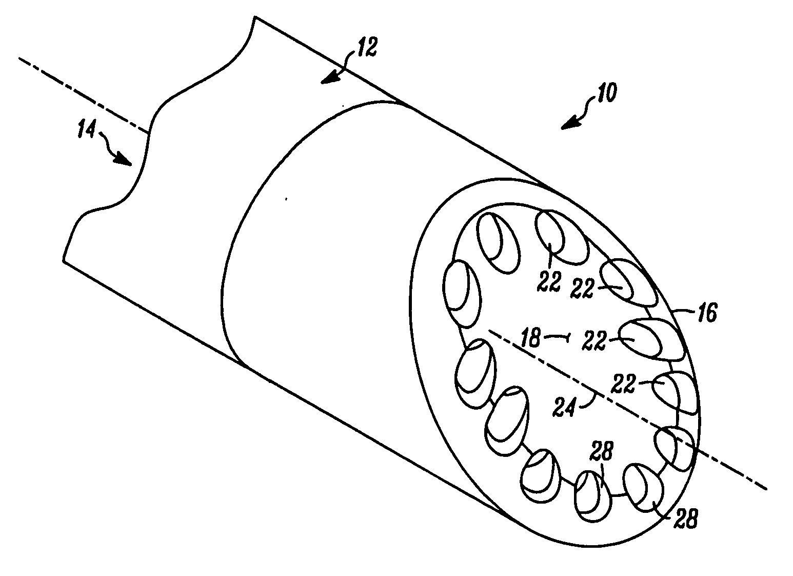
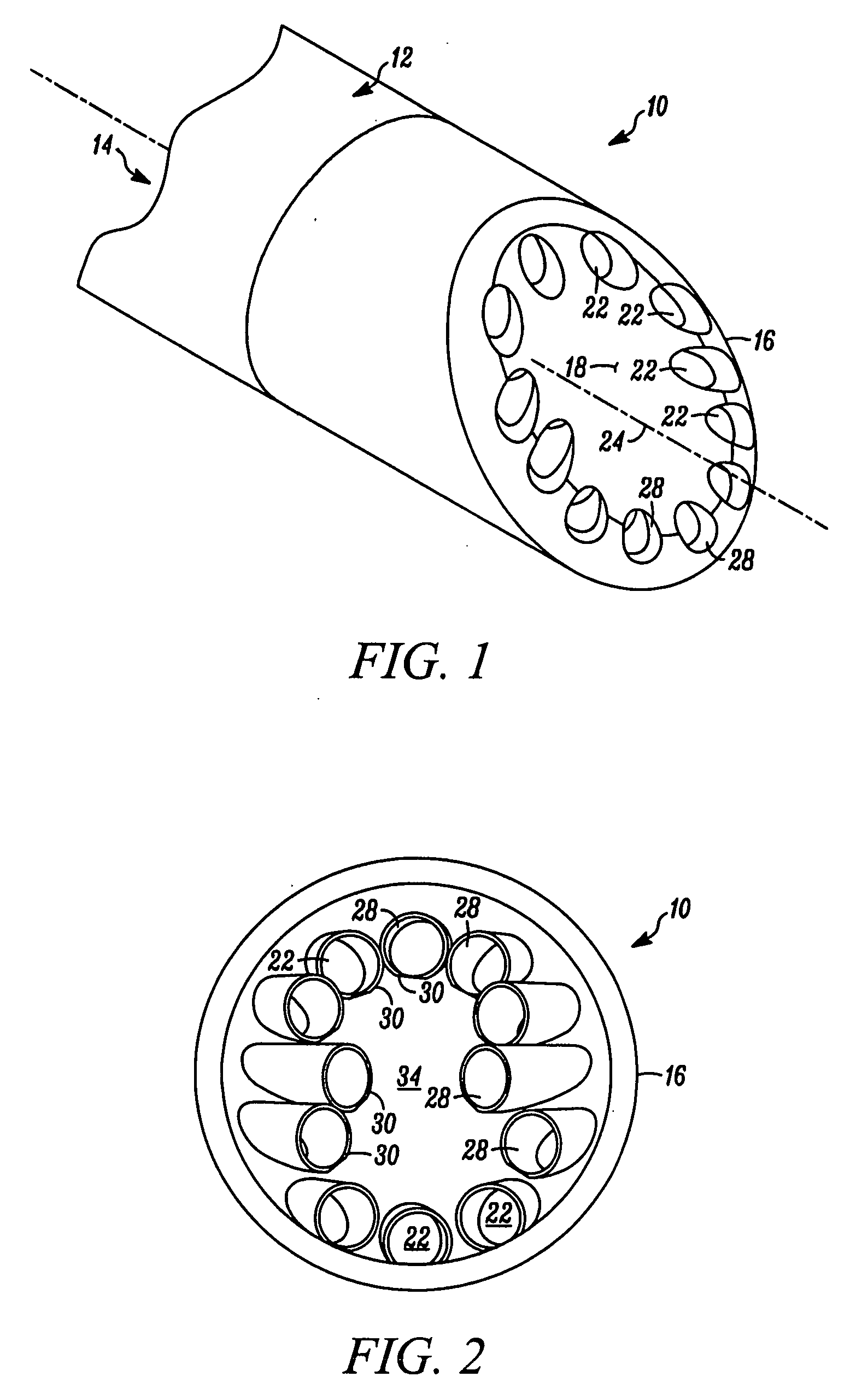
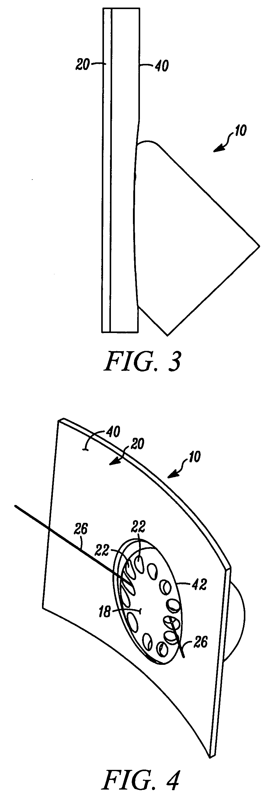
[0043] In FIGS. 1 through 8 a first embodiment of a nozzle of the present invention is indicated generally by the reference numeral 10. The nozzle 10 is for discharging first and second fluids in an atomized spray into a vessel 20 defining an internal contour. In one embodiment of the present invention the first fluid is oil, the second fluid is gas or steam, and the vessel is a catalytic cracking vessel. However, as may be recognized by those of ordinary skill in the pertinent art based on the teachings herein, the nozzles of the present invention are equally usable with any of numerous different types of fluids in connection with any of numerous different types of applications that are currently known, or that later become known.

[0044] The nozzle 10 comprises an inlet portion 12 defining at least one inlet conduit 14 for receiving at least one fluid and, in one embodiment, first and second fluids. An outlet portion 16 of the nozzle defines an exterior surface 18 that substantiall...


PUM

PropertyMeasurementUnit
diameteraaaaaaaaaa
diameteraaaaaaaaaa
temperaturesaaaaaaaaaa

Abstract

A nozzle for discharging first and second fluids in a spray pattern into a vessel, such as oil and steam in a catalytic cracking unit, includes various configurations for preventing erosion of the outlet portion of the nozzle that otherwise might be due, for example, to contact with a catalyst or other predetermined substance. In one such nozzle, the exterior surface of the outlet portion substantially conforms to the internal contour of the vessel. In another such nozzle, the outlet portion defines a plurality of substantially concentric, substantially elliptical-shaped outlet apertures. In another nozzle, the outlet portion is formed of ceramic and is connected to the inlet portion by a metal connector. In another nozzle, the outlet portion defines a plurality of apertures angularly spaced about a peripheral region of the outlet portion for discharging a substantially flat fan spray pattern, and a second outlet portion extending along an upstream portion of the outlet portion for discharging at least part of its spray to prevent any catalyst from contacting the downstream surfaces of the outlet portion.

Description

CROSS REFERENCE TO RELATED APPLICATIONS [0001] This application claims priority to U.S. Provisional Application No. 60 / 741,022, filed Nov. 29, 2005, the contents of which are hereby expressly incorporated by reference in their entirety as part of the present disclosure.FIELD OF THE INVENTION [0002] The present invention relates to spray nozzles, and more particularly, to spray nozzles that mix liquid and gas into an atomized spray. BACKGROUND OF THE INVENTION [0003] Fluidized catalytic cracking (FCC) is one of the major refining methods used in the oil refining industry. The FCC process is employed to crack materials consisting essentially of petroleum-type hydrocarbons to produce products such as fuels for internal combustion engines and heating oils. The cracking process is usually performed in a vertically oriented conduit, or riser including a reactor vessel, that forms part of an FCC system. During the process, hot catalyst particles in an aerated (fluidized) state are typicall...

Claims


Application Information

Patent Timeline
Patent Type & Authority Applications(United States)
IPC IPC(8): C10G11/00A62C31/02B05B1/00
CPCA62C31/05B05B1/04B05B7/067B05B7/06B05B1/14B01J8/1827B01J2208/00902B05B7/065
Inventor DZIADZIO, DOUGLAS J.DELESDERNIER, DANIEL T.BETSOLD, MATTHEW P.EMERSON, RONALD H.
Owner BETE FOG NOZZLE
Why Eureka
Try Eureka