Sensor array for nuclear magnetic resonance imaging systems and method

Active Publication Date: 2007-09-27
RADIATION MONITORING DEVICES
View PDF21 Cites 38 Cited by
  • Summary
  • Abstract
  • Description
  • Claims
  • Application Information

AI Technical Summary

Benefits of technology

[0013] The present invention generally provides improved devices, systems, and methods for measuring tissues and other materials with MRI. Exemplary embodiments provide a sensor array for NMR mapping and imaging of the material. Tissue can be measured with the sensor array mounted on a probe body having a distal portion that can be inserted through a minimally invasive aperture or body orifice. While many tissues can be measured and/or diagnosed, one exemplary embodiment includes a p

Problems solved by technology

Unfortunately, current techniques and apparatus used to diagnose diseases are often less than ideal, in some instances being ineffective and/or too complex or costly to implement on a routine clinical basis.
Failures and delays in diagnosing life threatening diseases such as cancer and atherosclerosis can lead to morbidity and/or mortality.
Atherosclerosis, a hardening and/or thickening of the arteries, is a leading cause of mortality and morbidity in the United States.
Treatments appropriate for standard stenotic plaques may be undesirable for such lesions, as a disruption of the fibrous cap integrity in these rupture-prone plaques may release procoagulant factors, resulting in thrombus formation and the potential for an acute coronary event.
Colon cancer is also a major cause of death, and can affect the population at a relatively early age.
Nevertheless, for a number of reasons, col

Method used


Image

  • Sensor array for nuclear magnetic resonance imaging systems and method
  • Sensor array for nuclear magnetic resonance imaging systems and method
  • Sensor array for nuclear magnetic resonance imaging systems and method

Examples


Example

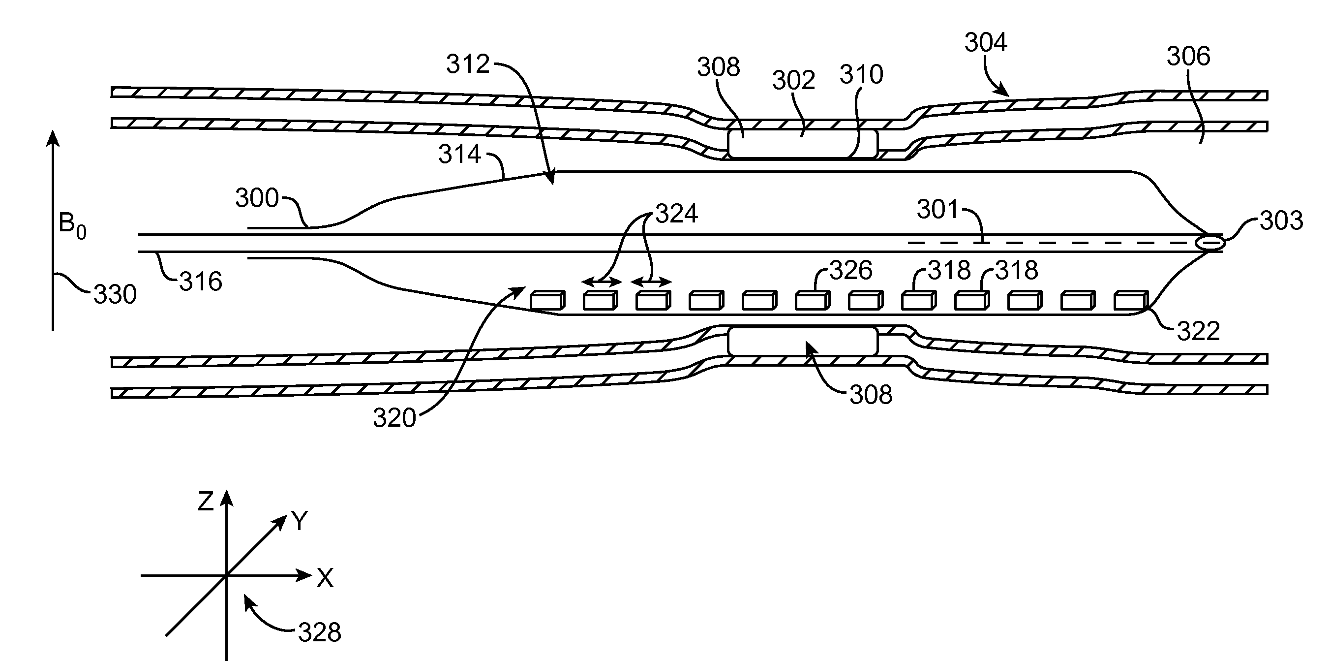
[0045] Embodiments of the present invention are directed to improved MRI systems and methods. Many of these systems incorporate sensors based on the anisotropic magnetoresistive effect or giant magnetoresistive effect (AMR and GMR, respectively). These magnetoresistive effects include, but are not limited to the anisotropic magnetoresistive effect, tunneling magnetoresistive effect, colossal magnetoresistive effect, and giant magnetoresistive effect. Many of the sensor arrays described herein permit the formation of images by direct signal localization, rather than by frequency encoding. Although embodiments will be discussed below in terms of a catheter probe to be used principally in the imaging of the coronary arteries, similar configurations can be used for examining suspicious areas of the colon identified during colonoscopy, or in broncoscopy, urography, or for examination of the skin, and other applications, for example NMR testing of ground water for contamination.

[0046] In...


PUM


Abstract

The present invention generally provides improved devices, systems, and methods for measuring materials with NMR and/or MRI. Exemplary embodiments provide a sensor array for NMR mapping of the material. For example tissue can be measured with the sensor array mounted on a probe body having a distal portion which can be inserted through a minimally invasive aperture. While many tissues can be measured and/or diagnosed, one exemplary embodiment includes a probe adapted for insertion into a lumen of a blood vessel. The sensor array can provide improved spatial resolution of tissue and/or tissue structures positioned near the sensor array to diagnose potentially life threatening diseases, for example a fibrous cap covering a vulnerable plaque. In specific embodiments, the sensors are attached to an expandable member, for example a balloon, which can be inflated to urge the probe sensors radially outward to position the sensors near the tissue structures.

Description

CROSS-REFERENCES TO RELATED APPLICATIONS [0001] Not Applicable STATEMENT AS TO RIGHTS TO INVENTIONS MADE UNDER FEDERALLY SPONSORED RESEARCH OR DEVELOPMENT [0002] Not Applicable REFERENCE TO A “SEQUENCE LISTING,” A TABLE, OR A COMPUTER PROGRAM LISTING APPENDIX SUBMITTED ON A COMPACT DISK. [0003] Not Applicable BACKGROUND OF THE INVENTION [0004] The present invention generally relates to the measurement of tissue and other materials, often so as to diagnose vulnerable plaque, colon cancer, and other diseases of tissues adjacent body lumens or the skin. Embodiments of the invention may employ insertable probes utilizing magnetic resonance imaging (MRI) and / or nuclear magnetic resonance (NMR) phenomena. [0005] Many diseases exist that can be successfully treated if diagnosed in a timely manner. Examples of such life threatening diseases that can be successfully treated include atherosclerosis and cancer. A variety of diagnostic imaging modalities have been developed to help diagnose the...

Claims


Application Information

Patent Timeline
IPC IPC(8): H01L41/00G01B7/30G01V3/00
CPCG01R33/286G01R33/323G01R33/5617G01R33/3415G01R33/3806G01R33/34084A61B5/062A61B5/6852A61B5/6853A61B5/687A61B2562/043A61B5/242A61B5/243
Inventor TIERNAN, TIMOTHY C.FORD, JOHN CHETLEY
Owner RADIATION MONITORING DEVICES
Why Eureka
Try Eureka