Method for decoding convolutionally coded signals and decoding apparatus and receiving apparatus using the same

Inactive Publication Date: 2007-09-27
SANYO ELECTRIC CO LTD
View PDF3 Cites 6 Cited by
  • Summary
  • Abstract
  • Description
  • Claims
  • Application Information

AI Technical Summary

Benefits of technology

[0022]According to this embodiment, as the number of corrections increases, the decoding selector switches the use f

Problems solved by technology

In the Viterbi decoding, the amount of processing is g

Method used


Image

  • Method for decoding convolutionally coded signals and decoding apparatus and receiving apparatus using the same
  • Method for decoding convolutionally coded signals and decoding apparatus and receiving apparatus using the same
  • Method for decoding convolutionally coded signals and decoding apparatus and receiving apparatus using the same

Examples


modification 1

[0110

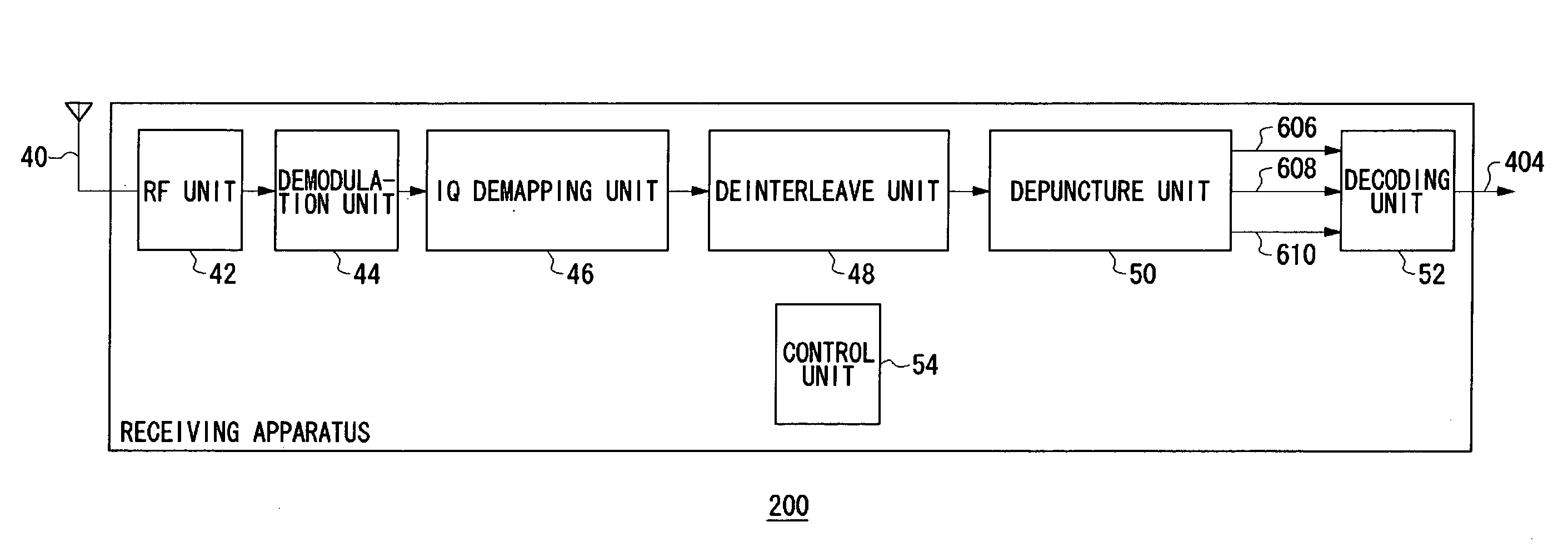
[0111]The not-shown SNR estimate unit is included in the demodulation unit 44 shown in FIG. 3. The SNR estimate unit measures the SNR of an intermediate frequency signal or a quadrature-detected baseband signal. This processing corresponds to measuring the strength of a received signal based on which the received data 402 are formed. The measured SNR corresponds to the quality of the received data 402. The SNR measurement unit outputs the measured SNR to the decoding unit 52 as the SNR estimate value 460.

[0112]The receiving control unit 114 compares the SNR estimate value 460 against a predetermined threshold value. If the SNR estimate value 460 is more satisfactory than the threshold value, the receiving control unit 114 will determine the execution of simplified decoding. As a result, the receiving control unit 114 generates a selection signal 470 by which to select the simplified decoding unit 112, and outputs the thus generated selection signal 470. If, on the other hand, t...

modification 2

[0114

[0115]When it starts the receiving processing, the receiving control unit 114 has the simplified decoding unit 112 perform the decoding and has the signal selector 116 output the decoded data from the simplifier decoding unit 112 as the final decoded data 404. The receiving control unit 114 receives the decoded data 404. It is assumed here that error check codes such as CRC are contained in the decoded data 404. The error check codes may be those used in a known technique. By the use of error check codes, the receiving control unit 114 can check whether the decoding has been done normally or not.

[0116]That is, the receiving control unit 114 accumulates the number of decoding error occurrences and compares it with a predetermined threshold value. This corresponds to evaluating the degree of error contained in the decoding result in the simplified decoding unit 112. If the number of occurrences becomes greater than the threshold value, the receiving control unit 114 will switch f...

modification 3

[0117

[0118]When starting a receiving processing, the receiving control unit 114 has the simplified decoding unit 112 perform the decoding and has the signal selector 116 output the decoded data from the simplified decoding unit 112 as the final decoded data 404. The receiving control unit 114 receives the verification error signal 416 from the simplified decoding unit 112, accumulates the number of occurrences of the verification error signal 416, and compares it with a predetermined threshold value. This corresponds to accumulating the cases when correction is done in the pattern verification unit 70. If the number of occurrences becomes greater than the threshold value, that is, if the number of performing the correction increases, the receiving control unit 114 will switch the use from the use of the simplified decoding unit 112 to the use of the Viterbi decoding unit 110. As a result, the Viterbi decoding unit 110 performs decoding and the signal selector 116 outputs the decoded...


PUM


Abstract

An input unit inputs sequentially bit data, where the bit data is convolutionally coded by a generator matrix defined according to a constraint length and a coding rate and has the number of streams defined by the coding rate. A temporary decoded data shift register unit delays temporary decoded data over at least a period of time corresponding to the constraint length. A generation unit generates, per stream, bit data serving as candidates for a decoding, by performing exclusive OR based on the generator matrix on the delayed temporary decoded data and the inputted bit data. A comparator and a selector select any of the bit data per stream generated by the generation unit, as a decoding result, and outputs the selected decoding result.

Description

BACKGROUND OF THE INVENTION[0001]1. Field of the Invention[0002]The present invention relates to a decoding technology and it particularly relates to a method for decoding convolutionally coded signals, and a decoding apparatus and a receiving apparatus utilizing said decoding method.[0003]2. Description of the Related Art[0004]One of coding techniques for correcting error of signals in a channel is the convolutional coding technique. The Viterbi decoder is a decoder that decodes convolutionally decoded signals. If this convolutional coding and the Viterbi decoding are combined together, a high error correction capability can be achieved (see Reference (1) enlisted in the following Related Art List, for instance).Related Art List[0005](1) Japanese Patent Application Laid-Open No. Hei05-244019.[0006]In recent years, the convolutaional coding technique has also been applied to the mobile communication, wireless LAN and the like. Accordingly, there is a growing need for the decoding of...

Claims


Application Information

Patent Timeline
IPC IPC(8): H03M7/00
CPCH03M13/23H03M13/3707H03M13/39H03M13/6575H03M13/6362H03M13/6502H03M13/41
Inventor HAMAMOTO, KATSUAKI
Owner SANYO ELECTRIC CO LTD
Why Eureka
Try Eureka