Scroll machine using floating seal with backer

a technology of scrolling machine and backer, which is applied in the direction of machines/engines, liquid fuel engines, rotary piston liquid engines, etc., can solve the problems of high isentropic and volumetric efficiency, extremely accurate and expensive machining techniques, and small and lightweight for a given capacity, so as to improve the durability of the polymer, improve the sealing design, and reduce the effect of stress

Inactive Publication Date: 2007-09-27
EMERSON CLIMATE TECH INC
View PDF12 Cites 10 Cited by
  • Summary
  • Abstract
  • Description
  • Claims
  • Application Information

AI Technical Summary

Benefits of technology

[0004] Scroll-type apparatus have been recognized as having distinct advantages. For example, scroll machines have high isentropic and volumetric efficiency, and hence are small and lightweight for a given capacity. They are quieter and more vibration free than many compressors because they do not use large reciprocating parts (e.g. pistons, connecting rods, etc.). All fluid flow is in one direction with simultaneous compression in plural opposed pockets which results in less pressure-created vibrations. Such machines also tend to have high reliability and durability because of the relatively few moving parts utilized, the relatively low velocity of movement between the scrolls, and an inherent forgiveness to fluid contamination.
[0012] The present invention provides the art with an improved seal design by providing a backer or backing plate which supports the polymer seal at the point of bending. The additional support provided by the backer significantly reduces the stresses associated with the seal during operation of the compressor and thus significantly improves the durability of the polymer.

Problems solved by technology

For example, scroll machines have high isentropic and volumetric efficiency, and hence are small and lightweight for a given capacity.
One of the difficult areas of design in a scroll-type machine concerns the technique used to achieve tip sealing under all operating conditions, and also at all speeds in a variable speed machine.
Conventionally, this has been accomplished by (1) using extremely accurate and very expensive machining techniques, (2) providing the wrap tips with spiral tip seals, which, unfortunately, are hard to assemble and often unreliable, or (3) applying an axially restoring force by axial biasing the orbiting scroll or the non-orbiting scroll towards the opposing scroll using compressed working fluid.
Second, a biasing load needs to be applied to the axially movable non-orbiting scroll to urge the non-orbiting scroll into engagement with the orbiting scroll.

Method used


Image

  • Scroll machine using floating seal with backer
  • Scroll machine using floating seal with backer
  • Scroll machine using floating seal with backer

Examples


Embodiment Construction

[0020] The following description of the preferred embodiment(s) is merely exemplary in nature and is in no way intended to limit the invention, its application, or uses.

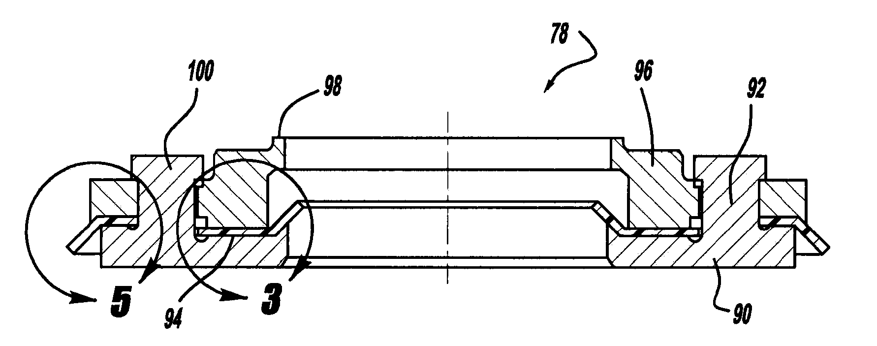
[0021] There is illustrated in FIG. 1 a scroll compressor which incorporates a floating seal arrangement in accordance with the present invention and which is designated generally by reference numeral 10. Compressor 10 comprises a generally cylindrical hermetic shell 12 having welded at the upper end thereof a cap 14 and at the lower end thereof a base 16 having a plurality of mounting feet (not shown) integrally formed therewith. Cap 14 is provided with a refrigerant discharge fitting 18 which may have the usual discharge valve therein (not shown). Other major elements affixed to the shell include a transversely extending partition 22 which is welded about its periphery at the same point that cap 14 is welded to shell 12, a stationary main bearing housing or body 24 which is suitably secured to shell 12, and a lowe...


PUM


Abstract

A floating seal has a lower plate, an upper plate and a pair of seals disposed between the two plates. The lower plate, the upper plate or both plates include a backer which projects outward from the plate to engage one or both of the seals to support the seal during operation.

Description

FIELD [0001] The present invention relates to floating seal designs for the axially movable scroll member of a scroll machine. More particularly, the present invention relates to a unique floating seal design for the axially movable non-orbiting scroll member of the scroll machine. BACKGROUND AND SUMMARY [0002] The statements in this section merely provide background information related to the present disclosure and may not constitute prior art. [0003] A class of machines exists in the art generally known as “scroll” machines for the displacement of various types of fluids. Such machines may be configured as an expander, a displacement engine, a pump, a compressor, etc., and the features of the present invention are applicable to any one of these machines. For purposes of illustration, however, the disclosed embodiments are in the form of a hermetic refrigerant compressor. [0004] Scroll-type apparatus have been recognized as having distinct advantages. For example, scroll machines h...

Claims


Application Information

Patent Timeline
Patent Type & Authority Applications(United States)
IPC IPC(8): F01C1/02F01C1/063
CPCF04C18/0215F04C27/005F04C23/008F04C27/008F04C28/24
Inventor WANG, ZHICHAO
Owner EMERSON CLIMATE TECH INC
Why Eureka
Try Eureka