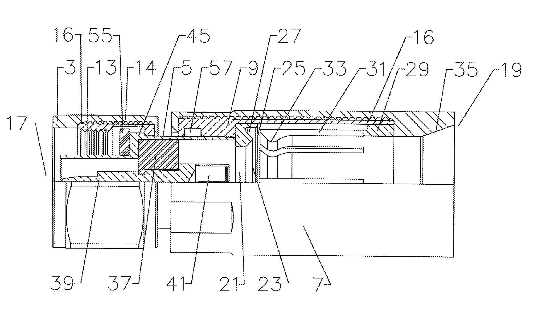
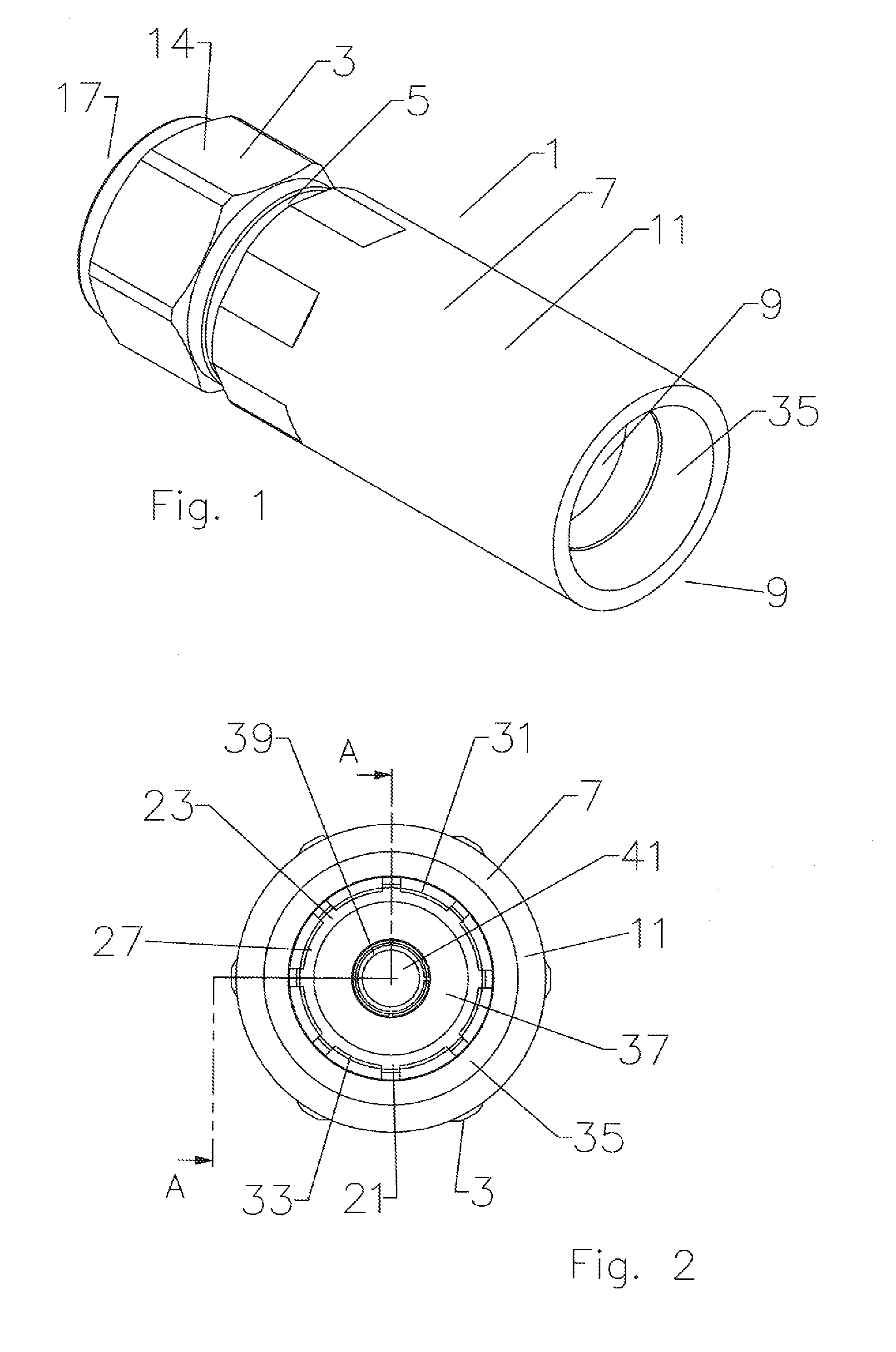
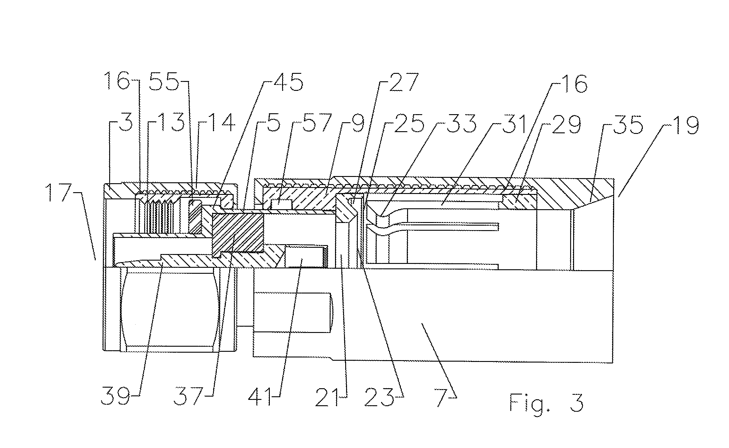
[0020] A connector 1 comprises a
coupling nut 3 surrounding an interface 5 which mates to a body 7. To reduce
metal materials requirements and decrease the overall weight of the connector 1, the body 7 may be formed with a body inner portion 9 and a body overmolding 11. Similarly, the
coupling nut 3 may be formed with a
coupling nut inner portion 13 and a coupling nut overmolding 14. The body and coupling nut overmolding(s) 11, 14 may be a polymeric material such as
polycarbonate or other plastic injection molded about the corresponding inner portion. A textured surface treatment 16 may be applied to the
metal inner body and coupling nut portions 9, 13 to improve adhesion with the overmolding.
[0021] As shown in FIG. 3, a connector 1 according to the invention is ready for installation upon a cable 15 without any
assembly / disassembly requirements. The body inner portion 9 and interface 5 are coupled together in an
interference fit along the connector end 17 bore of the body inner portion 9 and a corresponding cable end 19 outer
diameter of the interface 5. Within the connector 1 a
flare ring 21 is retained by an initial
interference fit within the body 7 and adjacent to a cable end 19 of the interface 5. The
flare ring 21 has a beveled
flare seat 23 and a retaining lip 25 that form an outer conductor groove 27 open to the cable end 19 of the connector 1. Alternatively, the beveled flare seat 23 and retaining lip 25 that form the outer conductor groove 27 may be formed in the cable end of the interface 5, eliminating the flare ring 21.
[0022] A spring finger ring 29, for example as shown in FIGS. 4 and 5, is located within the body 7 bore coupled to the cable end 19 of the body inner portion 9. The spring finger ring 29 has a plurality of spring finger(s) 31 extending towards the connector end 17. Each of the spring finger(s) 31 has an inward projecting bead 33 at the tip. The body overmolding 11 at the cable end 19 may be formed extending inward to an inner
radius of the spring finger ring 29 assisting with the retention of the spring finger ring 29 within the body inner portion 9 bore. Also, an angled face formed in the body overmolding 11 at the cable end 19 may provide a guide surface 35 for the
insertion of the cable 15 into the connector 1.
[0030] The invention provides an environmentally sealed connector 1 with improved installation characteristics. Depending upon the material characteristics and dimensions of the particular cable 15 used, the connector 1 may be quickly and securely attached using a compact
hand tool. Because threading between the body 7 and interface 5 has been eliminated by configuration for mounting via
axial compression, the body 7 and interface 5 do not need to be sized to support exterior
wrench flats and or threads between the interface 5 and the body 7. Therefore, even with larger
diameter cable(s) 15, the largest body 7 diameter may be easily configured to be less than the largest coupling nut 3 diameter which enables the installation of connectors and cables according to the invention in small spaces and or alongside each other in closer proximity. Because the factory pre-assembled connector 1 does not require any disassembly or other preparation before mounting upon a cable, the opportunity for losing or damaging an essential part of the connector 1 has been eliminated. In addition to reduced wall thickness requirements, through the application of overmolded polymeric outer surfaces and body 7 extensions, the connector 1 has significantly reduced weight.
[0031] The invention also provides significant manufacturing and materials cost efficiencies. The application of polymeric overmolding for outer surfaces significantly reduces the
metal content of the connector 1 while the inner portions of the body 7 and coupling nut 3 maintain a fully contiguous metallic electrical
enclosure with suitable levels of strength. Because the invention applies
axial compression to attach the connector 1 to a cable, threading is eliminated with respect to the clamping of the outer conductor. This allows the spring finger ring 29 to be permanently mounted within the body 7 without rotatability, greatly reducing the number of threading, shoulder, step and or groove
machining steps required during manufacture. Further, the greatly simplified surfaces of the body 7, interface 5 and or spring finger ring 29 according to the invention creates an opportunity for connector 1 component manufacture using cost effective
metal injection molding technologies. Table of Parts1connector3coupling nut5interface7body9body inner portion11body overmolding13coupling nut inner portion14coupling nut overmolding15cable16surface treatment17connector end19cable end21flare ring23flare seat25retaining lip27outer conductor groove29spring finger ring31spring finger33inward projecting bead35guide surface37insulator39center pin41spring basket43inner conductor45retention shoulder47outer conductor49sheath51leading edge53insulation55connector interface
gasket57interface
gasket groove


