Supercharge Your Innovation With Domain-Expert AI Agents!

Method of Packaging Integrated Circuit Devices Using Preformed Carrier

Inactive Publication Date: 2007-09-27
MICRON TECH INC
View PDF9 Cites 10 Cited by
  • Summary
  • Abstract
  • Description
  • Claims
  • Application Information

AI Technical Summary

Benefits of technology

[0008] The following presents a simplified summary of the invention in order to provide a basic understanding of some aspects of the invention. This summary is not an exhaustive overview of the invention. It is not intended to id

Problems solved by technology

Electronic products require packaged microelectronic devices to have an extremely high density of components in a very limited space.
For example, the space available for memory devices, processors, displays and other microelectronic components is quite limited in cell phones, PDAs, portable computers and many other products.
Reducing the size of a microelectronic device is difficult because high performance microelectronic devices generally have more bond pads, which result in larger ball / grid arrays and thus larger footprints.
The process described above, while acceptable in many applications, still suffers from said drawbacks.
For example, products may have to be scrapped due to problems encountered in the molding process, e.g., voids.
Moreover, the process described above may be very labor-intensive in that it requires that the molding apparatus be frequently cleaned.

Method used


Image

  • Method of Packaging Integrated Circuit Devices Using Preformed Carrier
  • Method of Packaging Integrated Circuit Devices Using Preformed Carrier
  • Method of Packaging Integrated Circuit Devices Using Preformed Carrier

Examples


Embodiment Construction

[0022] Illustrative embodiments of the invention are described below. In the interest of clarity, not all features of an actual implementation are described in this specification. It will of course be appreciated that in the development of any such actual embodiment, numerous implementation-specific decisions must be made to achieve the developers' specific goals, such as compliance with system-related and business-related constraints, which will vary from one implementation to another. Moreover, it will be appreciated that such a development effort might be complex and time-consuming, but would nevertheless be a routine undertaking for those of ordinary skill in the art having the benefit of this disclosure.

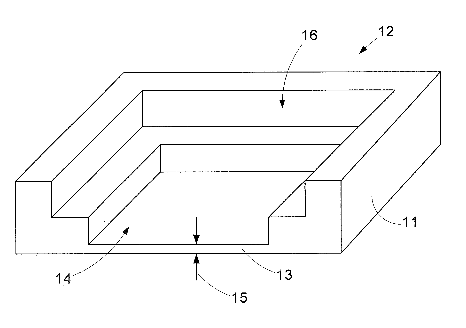
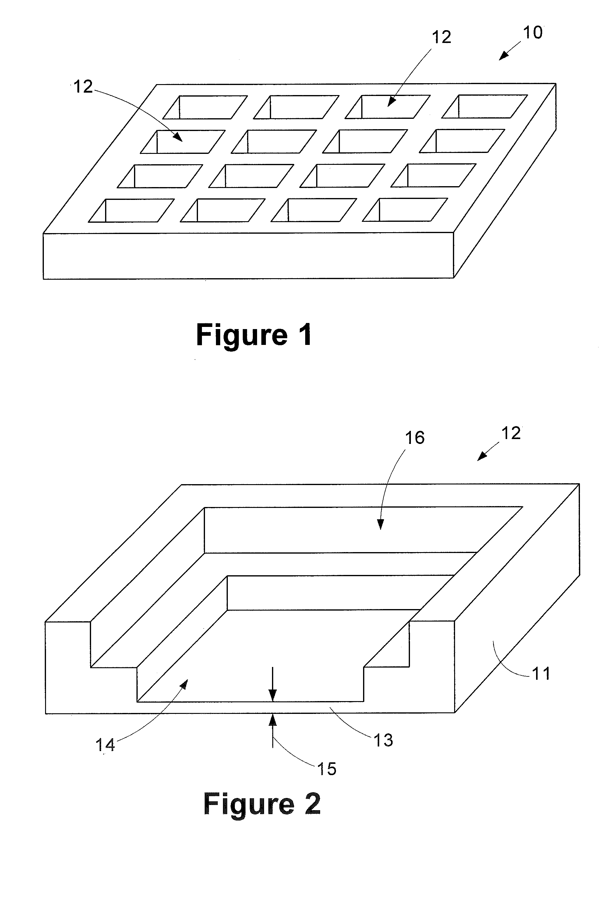
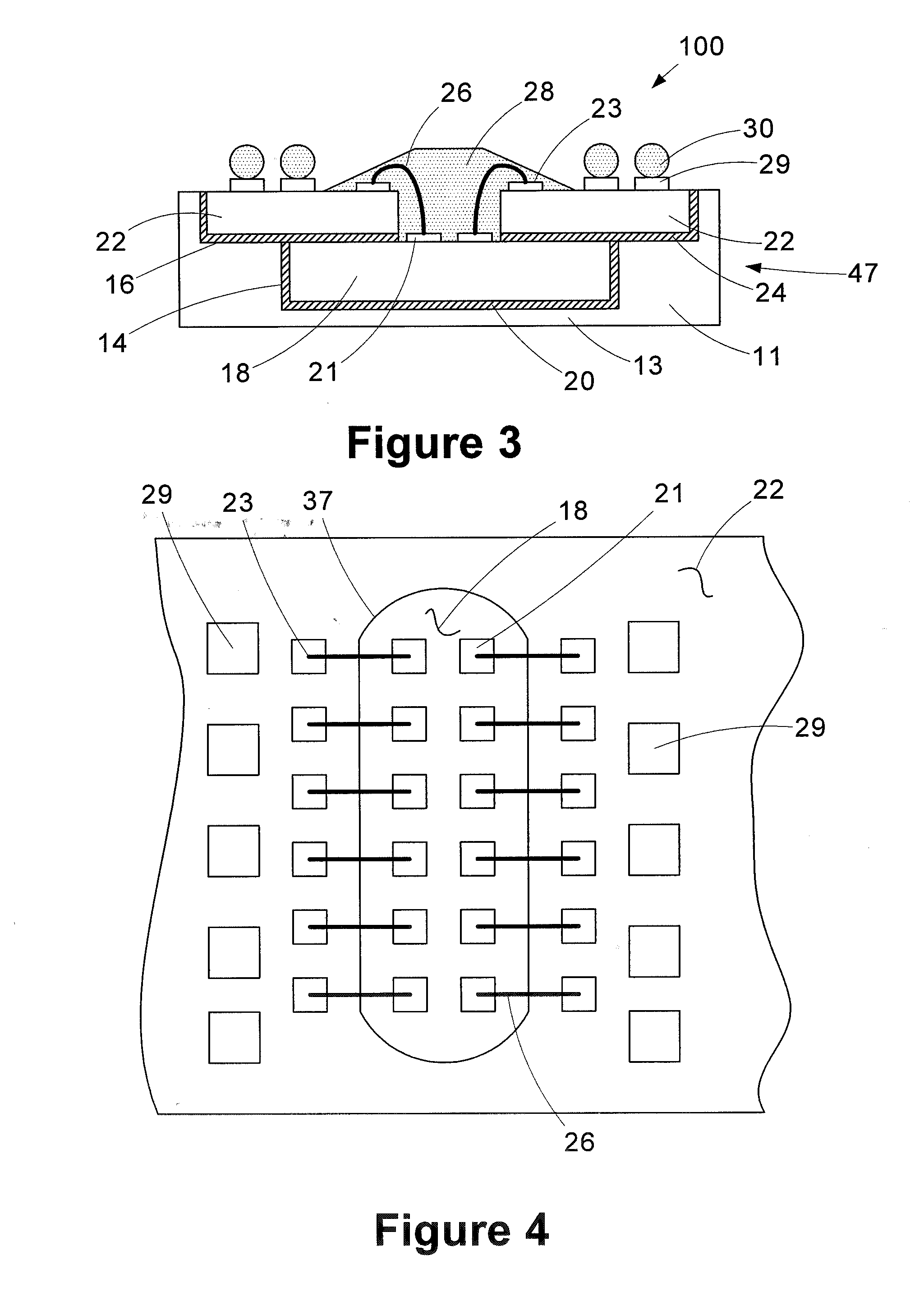
[0023] The present invention will now be described with reference to the attached figures. Various regions and structures of a packaged integrated circuit device are depicted in the drawings. For purposes of clarity and explanation, the relative sizes of the various features de...


PUM


Abstract

Disclosed is a method of packaging integrated circuit devices using a preformed carrier. In one illustrative embodiment, the method includes providing a carrier having a plurality of pockets formed therein, positioning an integrated circuit chip and a substrate in each of the plurality of pockets and conductively coupling the integrated circuit chip and the substrate in each of the plurality of pockets to one another. Also disclosed is a packaged integrated circuit device including a preformed body and an integrated circuit chip and a substrate positioned within the preformed body, the integrated chip and the substrate being conductively coupled to one another.

Description

BACKGROUND F THE INVENTION [0001] 1. Field of the Invention [0002] The present invention generally relates to the field of packaging integrated circuit devices, and, more particularly, to a method of packaging integrated circuit devices using a preformed carrier. [0003] 2. Description of the Related Art [0004] Microelectronic devices generally have a die (i.e., a chip) that includes integrated circuitry having a high density of very small components. In a typical process, a large number of die are manufactured on a single wafer using many different processes that may be repeated at various stages (e.g., implanting, doping, photolithography, chemical vapor deposition, plasma vapor deposition, plating, planarizing, etching, etc.). The die typically include an array of very small bond pads electrically coupled to the integrated circuitry. The bond pads are the external electrical contacts on the die through which the supply voltage, signals, etc. are transmitted to and from the integra...

Claims


Application Information

Patent Timeline
IPC IPC(8): G06F19/00
CPCH01L23/13H01L23/49816H01L2224/73215H01L24/49H01L23/49833H01L2224/4824H01L2224/49175H01L2924/01078H01L2924/14H01L2924/1433H01L2924/15311H01L24/48H01L2924/00H01L2924/00014H01L2224/32225H01L2924/181H01L2924/15153H01L2224/45099H01L2224/45015H01L2924/207
Inventor HONG, TAN
Owner MICRON TECH INC
Features
  • R&D
  • Intellectual Property
  • Life Sciences
  • Materials
  • Tech Scout
  • Unparalleled Data Quality
  • Higher Quality Content
  • 60% Fewer Hallucinations
Learn More