Method and apparatus for corrosion detection

a technology of corrosion detection and apparatus, applied in the direction of resistance/reactance/impedence, measurement devices, instruments, etc., can solve the problems of increasing the impedance the loss of material the increase of the material loss across the thickness of the sensor element, so as to inhibit the current flow through the device, reduce the impedance between the sensor and the backing element, and the effect of noise resistan

Active Publication Date: 2007-10-04
BL TECH INC
View PDF14 Cites 16 Cited by
  • Summary
  • Abstract
  • Description
  • Claims
  • Application Information

AI Technical Summary

Benefits of technology

[0007] The present invention provides a corrosion monitoring device adapted for monitoring corrosion in fluid containing systems and equipment. Although the present invention is described herein in terms of a corrosion monitoring device for use in fluid containing vessels and systems, the invention is also applicable for monitoring corrosion that occurs in valves, pumps, piping and any other equipment or material exposed to a corrosive environment. The present invention comprises at least one conductive sensor element fabricated from a conductive material having a composition substantially the same as the container or equipment being monitored. In one exemplary embodiment, a separator (i.e. insulator) element is located between a sensor element and a conductive backing element to form a layered sensor assembly. The sensor assembly is then installed in the fluid containing environment so as to expose the sensor element(s) to the processing fluid. An electric potential or current is applied between the sensor element and backing element. When the separator element remains dry, a virtual open circuit (high impedance) is provided between the sensor and backing elements, thereby inhibiting the flow of current through the device. Over time, a gradual loss of material occurs across the thickness of the sensor element due to the corrosive action of the processing fluid. Once the corrosion has penetrated through the predetermined thickness of the sensor element, the impedance between the sensor and backing elements is reduced, and the separator element becomes conductive due to wetting from exposure to the processing fluid, thus providing a virtual closed circuit and allowing current to flow through the device. The monitoring device communicates with a digital output device configured to output a first binary signal (e.g. ON, GO) indicating that corrosion has not penetrated through the thickness of the sensor element, and a second binary signal (e.g. OFF, NO-GO) indicating that corrosi

Problems solved by technology

Over time, a gradual loss of material occurs across the thickness of the sensor element due to the corrosive action of the processing fluid.
Over time, however, a gradual loss of material occurs across the thickness of the sensor element due to the corrosive action

Method used


Image

  • Method and apparatus for corrosion detection
  • Method and apparatus for corrosion detection
  • Method and apparatus for corrosion detection

Examples


example 1

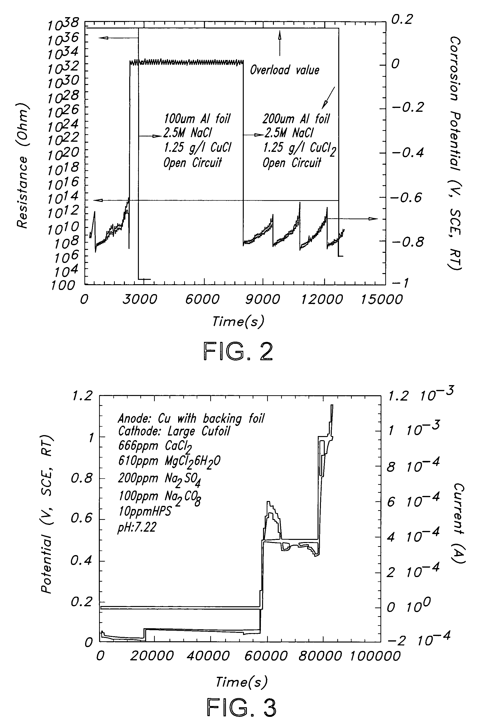
[0024] An aluminum foil of thickness 0.2 mm was exposed to 2.5M NaCl containing 1.25 g / l CuCl2. The resistance between the Al foil exposed to solution and another Al foil not exposed to solution are measured as a function of time. Initially the resistance is very high (in fact it is higher than the maximum value that the instrument can measure 110 MΩ). When corrosion has penetrated through the thickness of the exposed foil, there is a sharp change in resistance as seen in FIG. 2. Thus the time for corrosion to proceed through a given thickness can be determined. The time for corrosion to proceed through various thickness can also be measured to determine the kinetics of corrosion propagation as shown in FIG. 2 where foils of two different thickness were tested 0.1 mm and 0.2 mm.

example 2

[0025] Copper foils of two different thickness were tested in the solution chemistry shown in Table 1 below. An anodic potential of 0.5 V SCE and 1V SCE was applied using a three electrode setup. FIG. 3 is a graphical representation of potential and current versus time raw data plot illustrating the potential steps applied to the copper sample over the course of the experiment. The resistance is also measured and a change in resistance is indicative of corrosion penetrating through the thickness of the foil as shown in FIG. 4. In another set of experiments on copper foils of two different thickness (0.08 mm and 0.18 mm), potential steps were applied shown in FIG. 5. FIG. 6 demonstrates that resistance changes sharply when corrosion penetrates through the thickness of the foil.

TABLE 1Solution chemistry used in copper foil experiment.CaCl2666ppmMgCl2•6H2O610ppmNa2CO3100ppmNa2SO4200ppmPO42− (as Na4P2O7)2.5ppmPO42− (as NaHPO4)15ppmHPS10ppm

[0026] Turning now to FIG. 7, which illustrate...

example 3

[0029] A tantalum wire of 0.48 mm thickness was exposed to a methanol solution containing 0.93 wt % water and 0.5 wt % HCl. A potential of 1000 mV Ag / AgCl / 0.1M KCl was applied to accelerate corrosion. The resistance of the wire was measured continuously. Initially when the wire was continuous, the resistance was low as shown in FIG. 8. However, when pits or corrosion propagate through the diameter of the wire there is a sharp change in the resistance of the wire from about 10Ω to about 10 MΩ.

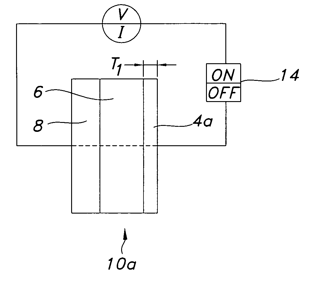
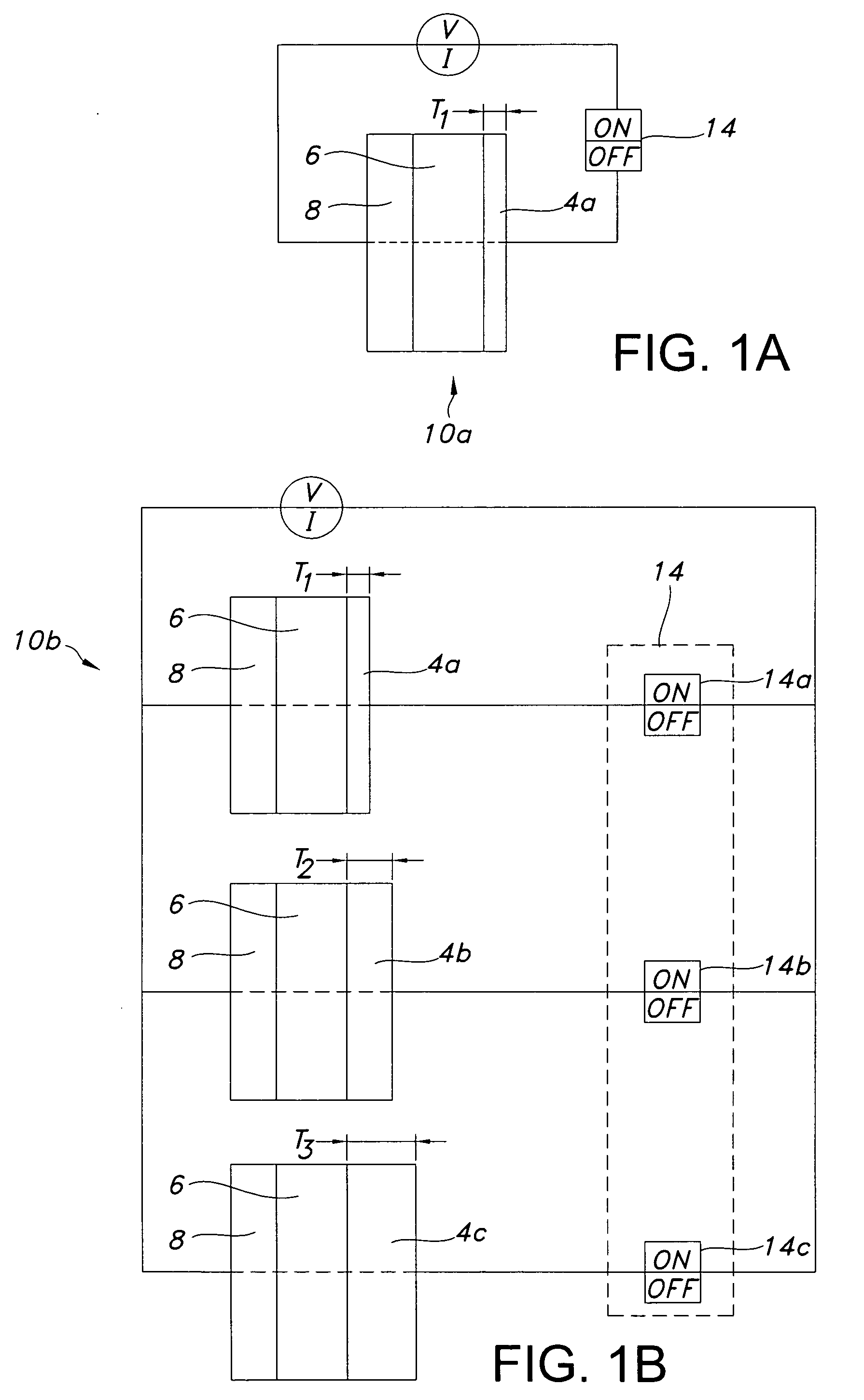
[0030] It is noted that the embodiment of FIG. 7 differs from the embodiments of FIGS. 1A, 1B and 9 in that electrical current initially flows through the sensor elements 40a, 40b, and 40c from the time the device is first installed in the fluid containing system, and current will continue to flow through the sensor elements 40a, 40b and40c until the loss of thickness in the respective sensor elements due to corrosive activity. As shown in FIG. 9, the 25 and 30 micron strips have failed, while ...


PUM


Abstract

A corrosion monitoring device for monitoring corrosion in fluid containing systems and other equipment exposed to a corrosive environment comprising sensor elements having a composition substantially the same as the equipment being monitored, the sensor elements having a predetermined thickness for exposure to a corrosive solution of the fluid containing system. An electrical property of the monitoring device changes when corrosion penetrates through the thickness of the sensor element. A digital output device generates a first binary signal when corrosion has not penetrated through the thickness of the sensor elements, and a second binary signal when corrosion has penetrated through the thickness of the sensor elements. Multiple sensor elements may be used to provide multiple binary signals. Information from the digital outputs may be processed to provide a cumulative log of corrosion measurements.

Description

BACKGROUND OF THE INVENTION [0001] 1. Field of the Invention [0002] The present invention relates generally to a system and method for measuring corrosion, and more particularly relates to a system and method for detecting localized corrosion in vessels, piping, valves, pumps, and other equipment exposed to a corrosive environment based on the time required for corrosion to proceed through a predetermined thickness of corrosion sensor material. [0003] 1. Description of Related Art [0004] Reliable corrosion monitoring of various process equipment is extremely important. For example, it is generally known that various industrial processes produce corrosive by-products. Such corrosive by-products frequently corrode industrial equipment, increase production costs, and create production delays. Thus, corrosion monitoring is a valuable tool which can alleviate such process upsets. Various attempts have been made using electrochemical (EC) and non-electrochemical techniques to identify cor...

Claims


Application Information

Patent Timeline
IPC IPC(8): G01R27/08
CPCG01N17/04
Inventor RAMGOPAL, THODLANELSON, J. LAWRENCELASIUK, BRIANESMACHER, MEL JOSEPHCROVETTO, ROSEPARKER, WILEY LYLE
Owner BL TECH INC
Why Eureka
Try Eureka