Circuit having enhanced input signal range

a technology of input signal and circuit, applied in the field of electronic circuits, can solve the problems high power dissipation of comparator circuits employing all io devices, and lack of low input signal swing, so as to increase the operable range of input signal levels and increase power consumption.

Active Publication Date: 2007-10-04
AVAGO TECH INT SALES PTE LTD
View PDF9 Cites 11 Cited by
  • Summary
  • Abstract
  • Description
  • Claims
  • Application Information

AI Technical Summary

Benefits of technology

[0006] The present invention meets the above-noted need by providing, in an illustrative embodiment thereof, an improved comparator circuit configured to accept a wide range of input signal levels and therefore suited for operation with a variety of IO interface standards, including, but not limited to, HSTL, SSTL and GTL. Moreover, the improved comparator circuit advantageously increases the operable range of input signal levels without significantly increasing power consumption in the comparator circuit and without the addition of voltage level translation circuitry which can undesirably introduce significant delay into the comparator circuit.

Problems solved by technology

A comparator circuit employing all IO devices, however, typically has high power dissipation and lacks the ability to accept low input signal swings.
This limits the applicability of such circuits to signaling levels that are typically greater than about 1.2 volts.
On the other hand, a comparator circuit employing all core devices cannot accept high input signal swings without undesirably impacting reliability.

Method used


Image

  • Circuit having enhanced input signal range
  • Circuit having enhanced input signal range
  • Circuit having enhanced input signal range

Examples


Embodiment Construction

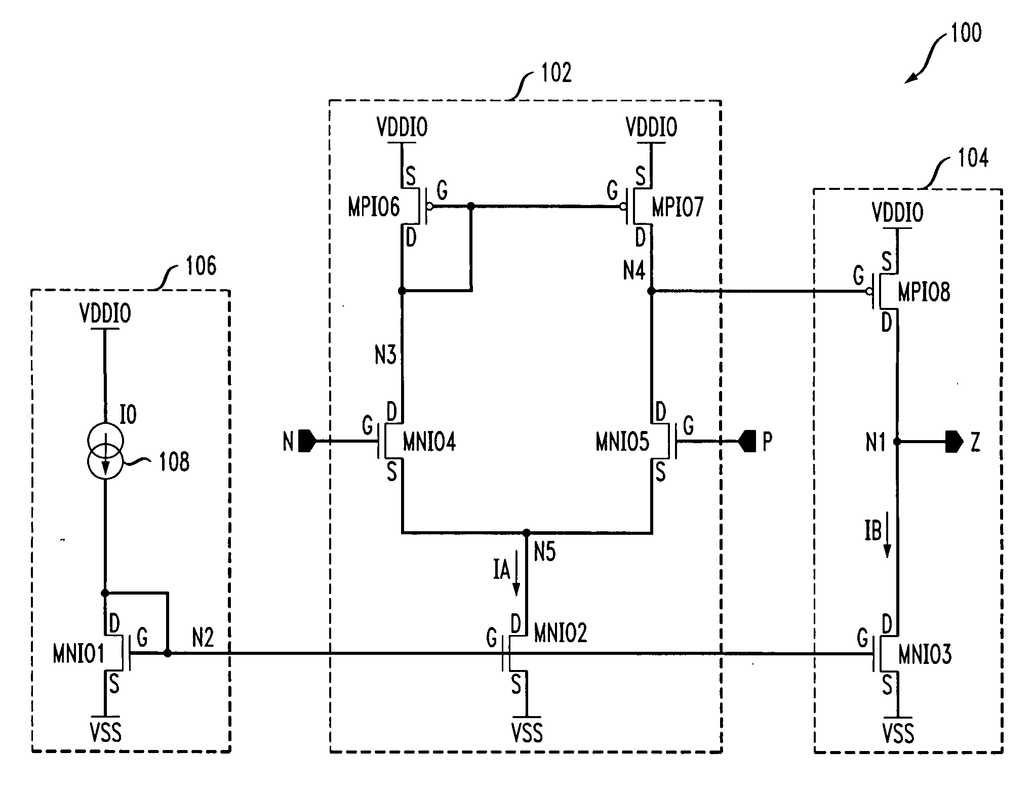
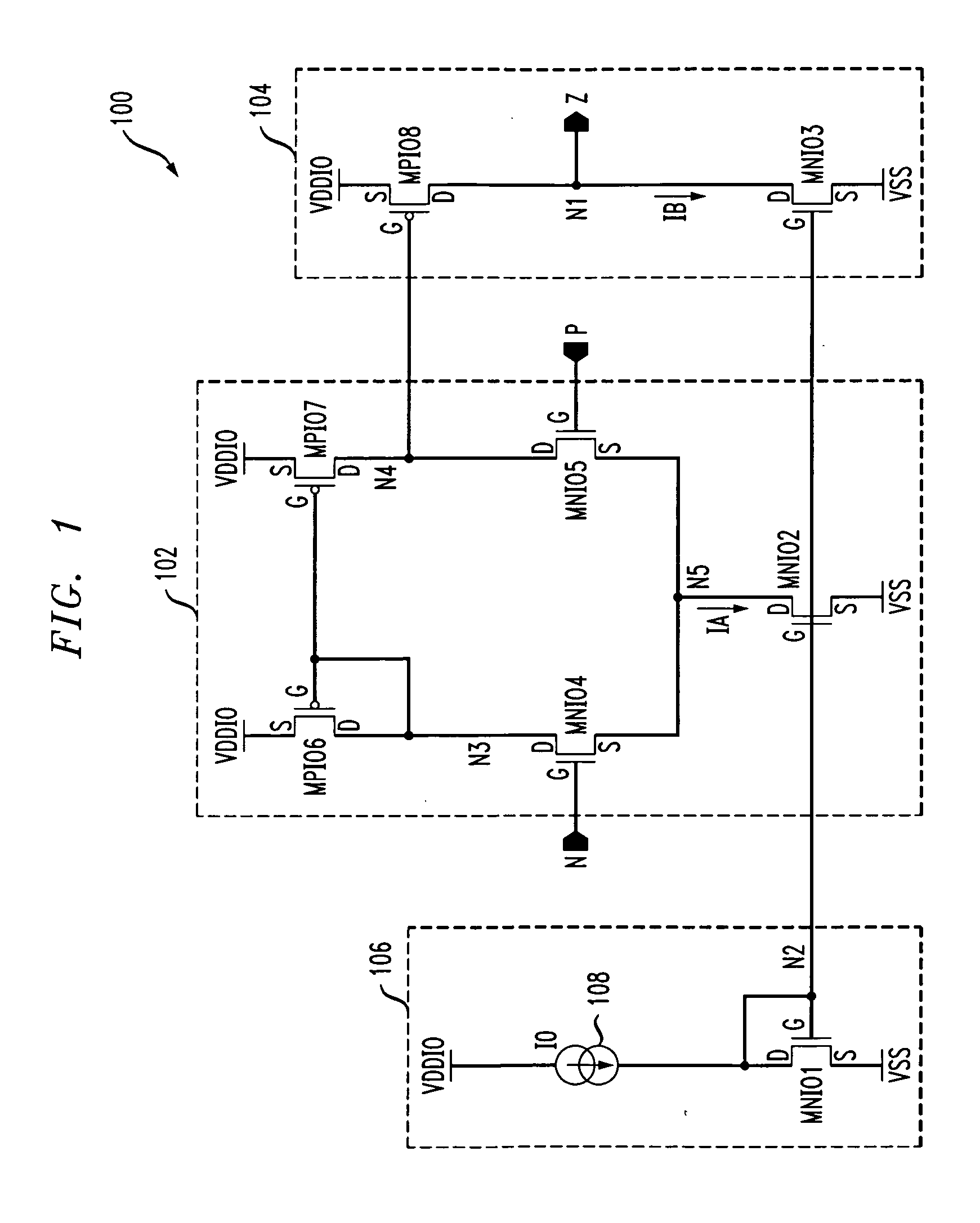
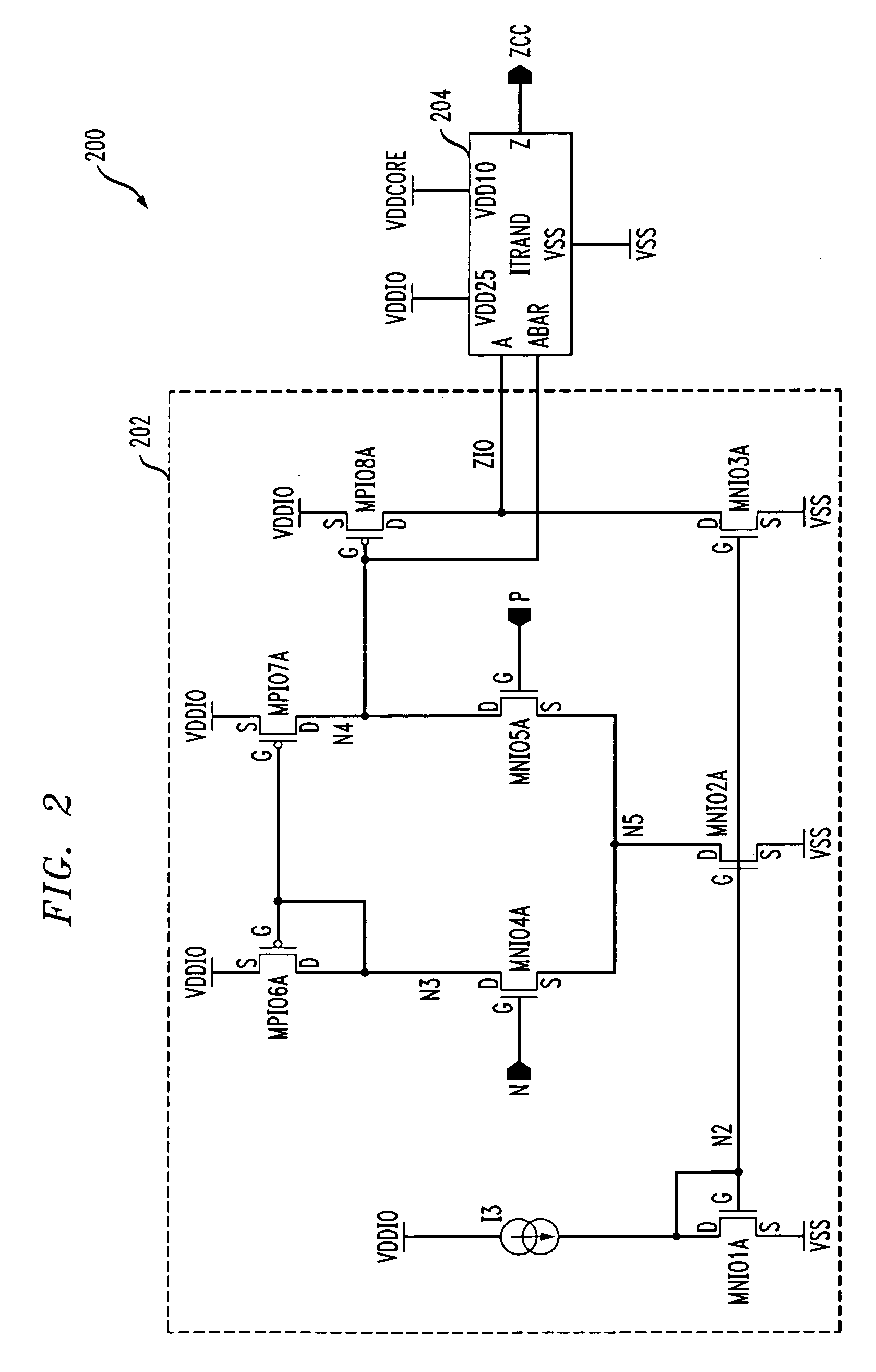
[0015] The present invention will be described herein in the context of illustrative comparator circuits. It should be understood, however, that the present invention is not limited to these or any particular comparator circuit arrangements. Rather, the invention is more generally applicable to techniques for advantageously enhancing the range of input signal swing in a circuit without significantly increasing power consumption in the circuit. Furthermore, although implementations of the present invention are described herein with specific reference to n-channel metal-oxide semiconductor (NMOS) transistor devices and p-channel metal-oxide semiconductor (PMOS) transistor devices, as may be formed using a complementary metal-oxide semiconductor (CMOS) fabrication process, it is to be appreciated that the invention is not limited to such transistor devices and / or to such a fabrication process, and that other suitable devices, such as, for example, bipolar junction transistors, etc., an...


PUM


Abstract

A circuit having an enhanced input signal range includes a differential amplifier operative to receive at least first and second signals and to amplify a difference between the first and second signals. The differential amplifier generates a difference signal at an output thereof which is a function of the difference between the first and second signals. The differential amplifier includes an input stage having at least first and second transistors operative to receive the first and second signals, respectively, each of the first and second transistors having a first threshold voltage associated therewith, and a load including at least third and fourth transistors having a second threshold voltage associated therewith, the first threshold voltage being greater than the second threshold voltage. The circuit further includes an output stage coupled to the differential amplifier and being operative to receive the difference signal and to generate an output signal of the circuit, the output signal being indicative of the difference signal and being referenced to the first voltage. The circuit is configured to accept the first and second signals having a voltage swing which is potentially greater than a supply voltage of the circuit.

Description

FIELD OF THE INVENTION [0001] The present invention relates generally to electronic circuits, and more particularly relates to techniques for increasing input signal range in a circuit. BACKGROUND OF THE INVENTION [0002] Comparators are well known in the art. A comparator is a circuit which compares one input signal with at least another input signal and outputs a binary signal based on the result of the comparison. In the case of an analog comparator, the two or more input signals to be compared are generally analog in nature. What is meant here by an analog signal is one that can have one of a continuum of amplitude values at any given point in time. In many applications, it is desirable to provide a binary output signal indicating when an input signal is above or below a predefined reference level. In this scenario, a substantially fixed reference voltage is applied to one of the inputs of the comparator, and the other input of the comparator receives the input signal to be compa...

Claims


Application Information

Patent Timeline
Patent Type & Authority Applications(United States)
IPC IPC(8): H03F3/45
CPCH03F3/45183H03F2200/513H03F2200/78H03F2203/45684H03F2203/45361H03F2203/45552H03F2203/45314
Inventor BHATTACHARYA, DIPANKARKOTHANDARAMAN, MAKESHWARKRIZ, JOHN C.MORRIS, BERNARD L.
Owner AVAGO TECH INT SALES PTE LTD
Why Eureka
Try Eureka