Wireless Gate Control and Communication System

a technology of communication system and gate control, applied in the direction of program control, instruments, anti-theft devices, etc., can solve the problems of not always being reliable and requiring expensive trenching, and achieve the effects of low power requirement, low cost and high efficiency

Inactive Publication Date: 2007-10-04
THE CHAMBERLAIN GRP INC
View PDF10 Cites 24 Cited by
  • Summary
  • Abstract
  • Description
  • Claims
  • Application Information

AI Technical Summary

Benefits of technology

[0008] Another object is to provide a gate control and communications system for use in access control devices which has extremely low power requirements, permitting practical operation with standard or solar rechargeable batteries.
[0009] A further object is to provide an access control system including a gate control unit and communications system which offers a full range of functionality, is extremely reliable and, at the same time, lower in cost than comparable prior art systems.
[0010] Other objects will in part be obvious and will in part appear hereinafter.
[0011] In accordance with the foregoing objects and advantages, the present invention provides a three-part system, namely, a base unit, a gate receiver unit and a gate control unit, the latter being hereinafter referred to as a GCU. The base unit is located at or within the premises and comprises a transceiver designed to interface with the other two parts. That is, the base unit permits an individual at the premises to respond to a call from the GCU, provides two-way voice communication between the premises and the GCU, and permits command signals to be communicated from the premises to the GCU to open the gate.
[0012] The gate receiver unit comprises an output switching device such as a relay or a similar semiconductor device that will command the gate operator to open the gate when a valid signal and command is rec

Problems solved by technology

Although some access control systems employ solar power, this may not always be reliable and the usual practice is to connect the gate motor co

Method used


Image

  • Wireless Gate Control and Communication System
  • Wireless Gate Control and Communication System
  • Wireless Gate Control and Communication System

Examples


Embodiment Construction

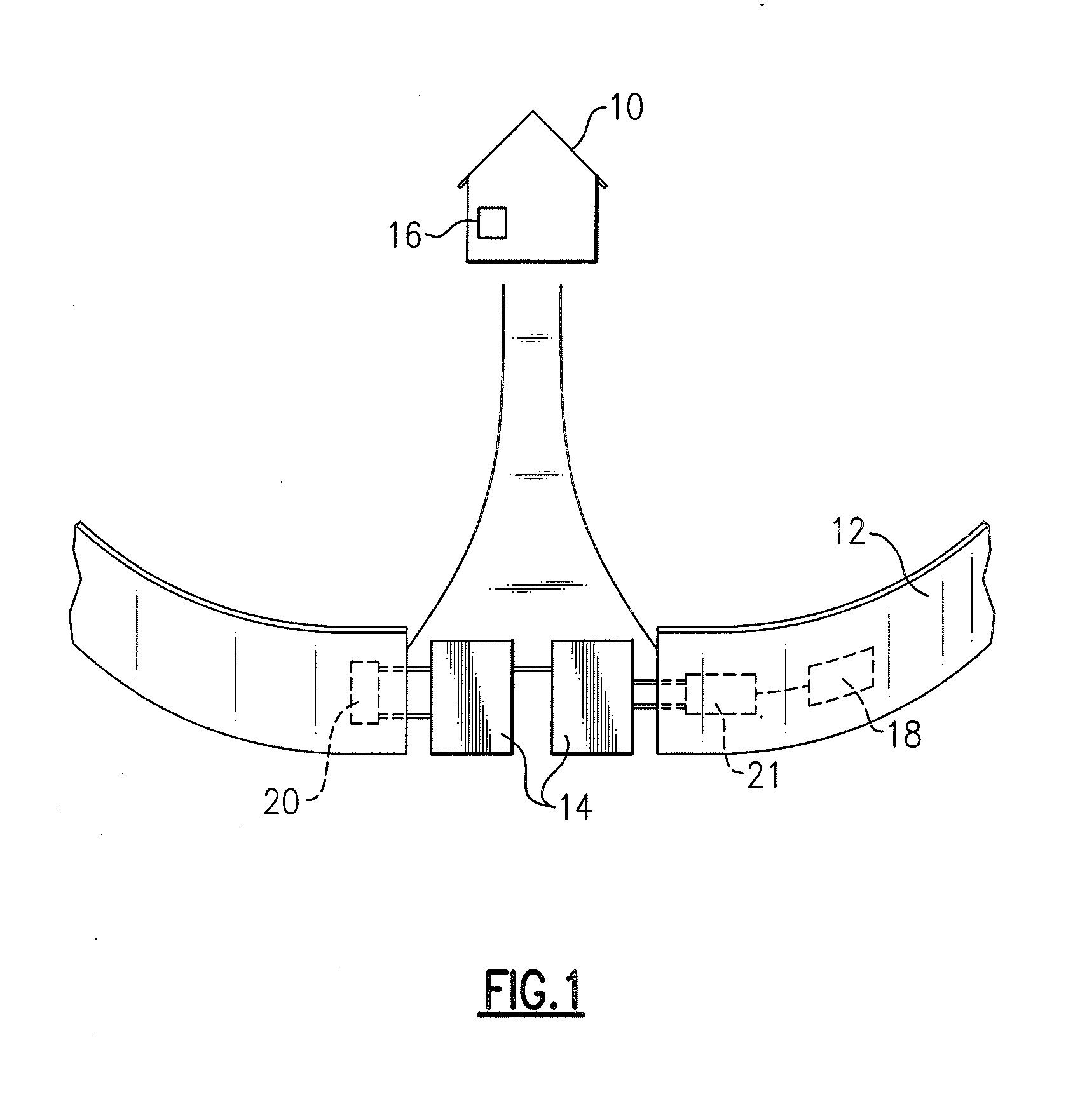
[0025] Referring now to the drawings, wherein like reference numerals refer to like parts throughout, there is seen in FIG. 1 a residential or commercial building 10, herein referred to as a premises, surrounded entirely or partially by a fence or wall 12 at some distance from premises 10. A movable barrier, such as gate 14, is movable between unblocking and blocking (open and closed, respectively) positions with respect to an opening in wall 12. Boxes 16, 18 and 20 indicate three units making up the system of the invention, namely a base unit 16, a gate receiver unit 18 and a gate control unit 20, respectively, each separately described in some detail hereinafter. Box 21 represents a gate operating device, such as an electric motor, for physically moving gate 14 between its open and closed positions.

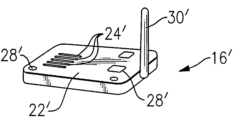
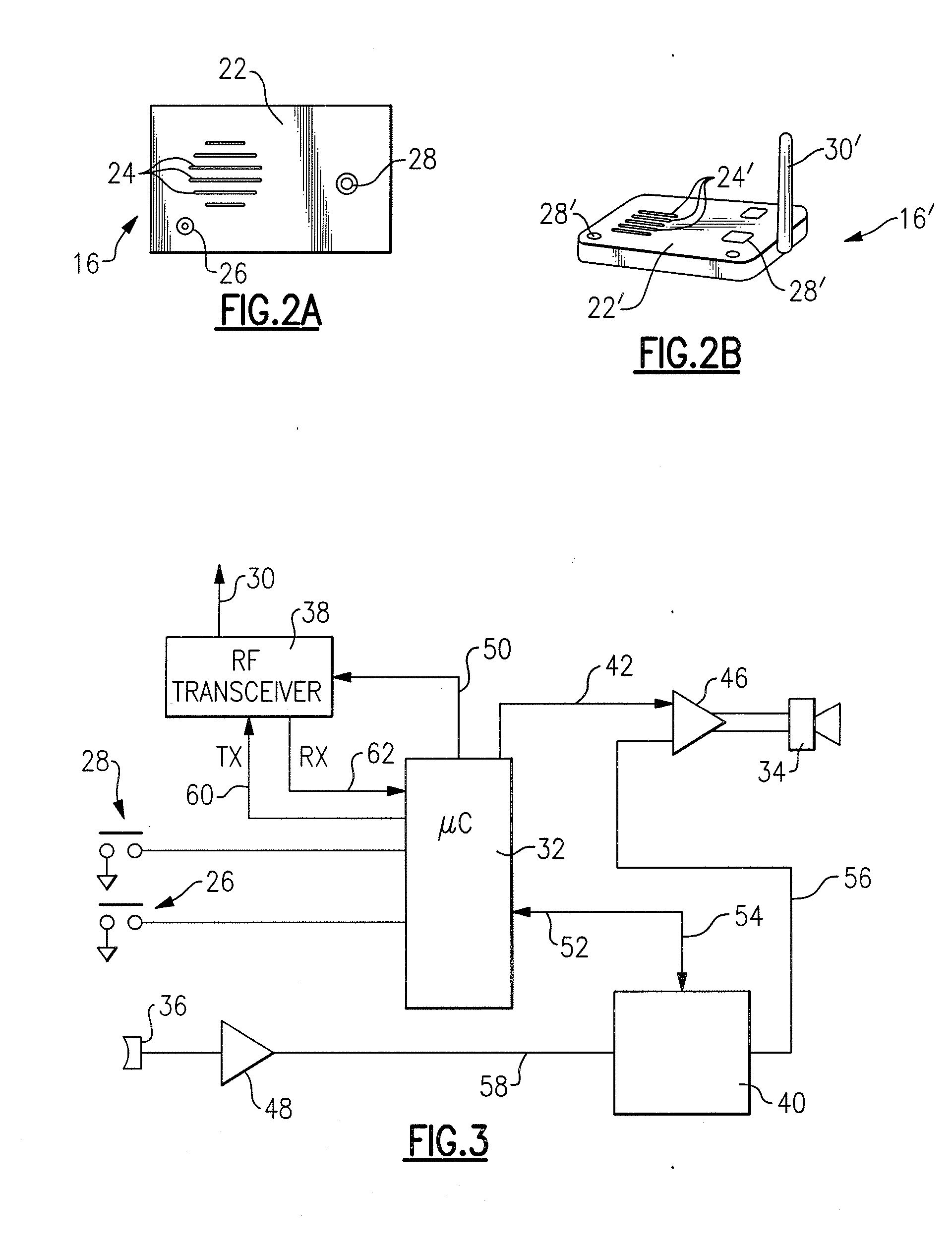
[0026] Base unit 16 is shown in FIG. 2A as it might appear in a stationary mounting at premises 10. Plastic or metal face plate 22 is flush mounted to a wall of premises 10 and include...


PUM


Abstract

A gate control and communication system of the invention including a base unit located within a premises, a gate receiver unit positioned next to a remotely located gate, and a gate control unit located next to the gate. The base unit provides for voice communications with an individual at the gate and for issuing of commands to control the gate. The gate receiver unit includes a switching device which, in response to commands directs the opening and closing of the gate. The gate control unit includes a call button for initiating voice communication with the base unit and a keypad for entering an identification code or password.

Description

CROSS-REFERENCE TO RELATED APPLICATIONS [0001] This application claims priority to U.S. Provisional Patent Application Ser. No. 60 / 767,285, filed Mar. 15, 2006.BACKGROUND OF THE INVENTION [0002] 1. Field of the Invention [0003] The present invention relates to control of access to secured locations, as when a door or gate is positioned to block entry to a residential or business premises and is opened or released in response to a coded input, in association with a system providing communication between the vicinity of the gate and the premises. [0004] 2. Description of the Related Art [0005] Physical access to many residential and commercial premises is controlled by placing a movable barrier such as a gate or door in a fence or wall and installing a control system to unlock and / or physically move the barrier to an open position, permitting access to the secured premises, in response to an electrical signal. This input signal may be generated in response to a coded input entered on ...

Claims


Application Information

Patent Timeline
IPC IPC(8): G05B19/00
CPCG07C9/00126G07C9/00309G07C2009/00793H04M11/025G08C17/00G08C2201/31G07C2009/00928G07C9/30
Inventor NASSIMI, SHARY
Owner THE CHAMBERLAIN GRP INC
Why Eureka
Try Eureka