Planar Antenna Module, Triple Plate Planar, Array Antenna, and Triple Plate Feeder-Waveguide Converter

Inactive Publication Date: 2007-10-04
HITACHI CHEM CO LTD
View PDF3 Cites 20 Cited by
  • Summary
  • Abstract
  • Description
  • Claims
  • Application Information

AI Technical Summary

Benefits of technology

[0028] According to yet another embodiment, there is provided an inexpensive, easy-to-assemble triple plate feeder—waveguide converter that is able to make unnecessary the short-circuit metal plate 180 and the short-circuit length adjustment metal plate 190, both of which have been required in a conventional structure, without impairing a low loss characteristic that ha

Problems solved by technology

Therefore, there exists a disadvantage in that the insertion loss becomes larger when using a casting method than when using a cutting work product to make the ground plates (14) (19) and thus cost reduction becomes difficult.
It has been known that the traverse component is then radiated out from the adjacent slot, thereby placing an adverse effect on an array-antenna gain, the effect being caused due to a phase relation with the component radiated directly outward from the slot.
As descr

Method used


Image

  • Planar Antenna Module, Triple Plate Planar, Array Antenna, and Triple Plate Feeder-Waveguide Converter
  • Planar Antenna Module, Triple Plate Planar, Array Antenna, and Triple Plate Feeder-Waveguide Converter
  • Planar Antenna Module, Triple Plate Planar, Array Antenna, and Triple Plate Feeder-Waveguide Converter

Examples


first embodiment

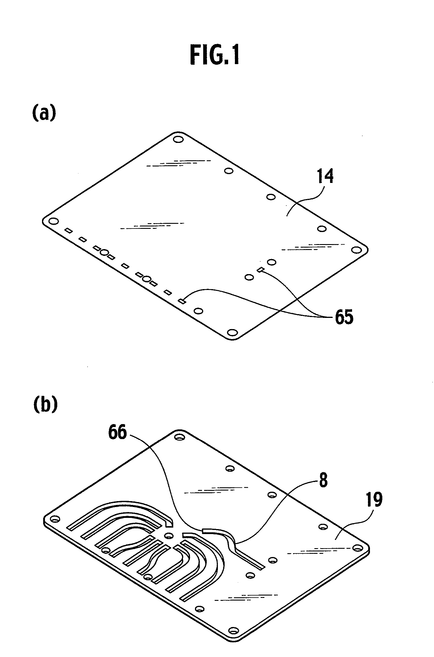
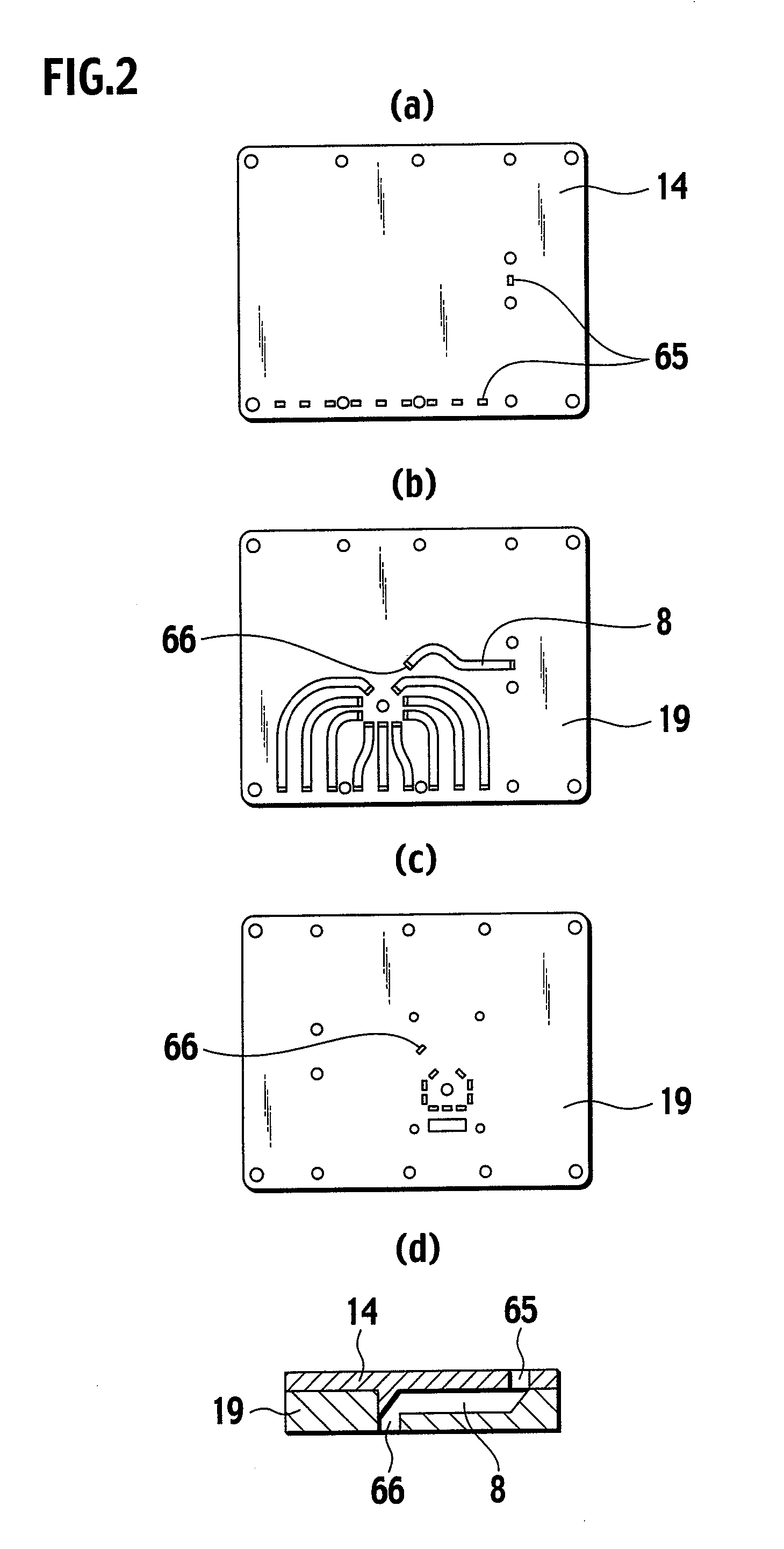
[0067] Referring to FIGS. 4, 5, and 7, in the planar antenna module according to the first embodiment of the present invention, the radiation element 41 serves as an antenna element along with the fourth ground plate 14 and the first slot 21 formed in the first ground plate 11 and is able to take in energy having a predetermined frequency. The energy is transferred to the first connection portion 43 by the first feeder 42 formed on the antenna substrate 40. The energy is then transferred to the second feeder 51 because the first connection portion 43 formed in the antenna substrate 40 is electromagnetically coupled with the second connection portion 52 formed in the feed substrate 50 via the second slot 24 formed in the fourth ground plate 14.

[0068] In this case, the first connection port formation portion 22 formed in the second ground plate 12, the second connection port formation portion 23 formed in the third ground plate 13, the third connection port formation portion 25 forme...

example 1

[0077] An example according to the first embodiment is described with reference to FIGS. 4, 5, and 7.

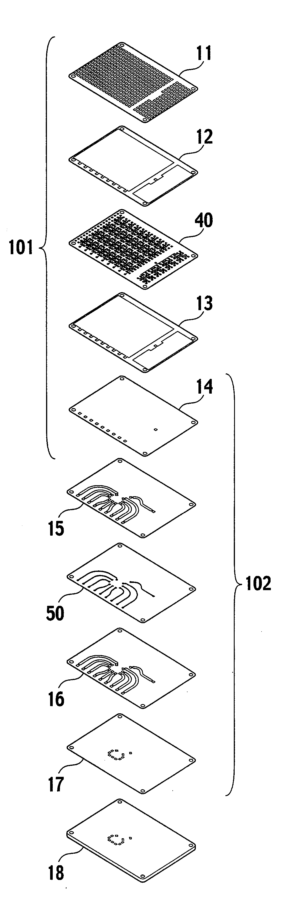
[0078] The first ground plate 11, and the fourth plate 14 were made of an aluminum plate of 0.7 mm thick. The second ground plate 12, the third ground plate 13, the fifth ground plate 15, the sixth ground plate 16, and the seventh ground plate 17 were made of an aluminum plate of 0.3 mm thick. The (circuit) connection plate 18 was made of an aluminum plate of 3 mm thick. The dielectrics 31, 32, 33, 34 were made of foamed polyethylene having a relative permittivity of 1.1 relative to air and a thickness of 0.3 mm. The antenna substrate 40 and the feed substrate 50 were made using a flexible substrate in which a copper foil has been attached on a polyimide film. Specifically, the antenna substrate 40 was made by etching off an unnecessary portion of the copper foil to form the radiation elements 41, the first feeders 42, the first connection portions 43, the second feeders 51, the sec...

second embodiment

[0082] A planar array antenna according to a second embodiment is characterized in that dielectrics 2a, 2b and metal spacers 9a, 9b having the same thickness are provided as a metal shield portion so as to sandwich an antenna circuit substrate 3 therebetween, and dummy slot openings 8 adjacent to a slot opening 7 in a slot plate 4 are provided, as illustrated in FIG. 15(a).

[0083] Another planar array antenna according to this embodiment is characterized in that an arrangement distance of the dummy slot openings 8 concerned is from 0.85 to 0.93 times the free space wavelength λ0 of the center frequency of a frequency band to be used, as illustrated in FIG. 15(b).

[0084] Yet another planar array antenna according to this embodiment is characterized in that dummy elements 10 that are similar to the radiation elements 5 in terms of size are provided on the antenna circuit substrate 3 so that the dummy slot openings 8 are positioned directly thereabove, as illustrated in FIGS. 16(a), 16...


PUM


Abstract

The present invention provides inexpensively a planar antenna module that is able to realize a loss reduction, a reduction in characteristic variation caused by an assembling error, and an improved stability in frequency characteristics.
A planar antenna module according to one preferred embodiment of the present invention comprises an antenna portion (101), a feeder portion (102), and a connection plate (18). The antenna portion (101) includes a first ground plate (11) having a first slot (21), a second ground plate (12) having dielectrics, an antenna substrate having a radiation element (41), a third ground plate (13) having dielectrics, a fourth ground plate (14). The feeder portion (102) includes the fourth ground plate (14), a fifth ground plate (15), a feed substrate (50), a sixth ground plate (16), a seventh ground plate (17). The connection plate (18) has a second waveguide opening portion (64). The connection plate (18) to be connected with a high frequency circuit, the seventh ground plate (17), the sixth ground plate (16), the feed substrate (50), the fifth ground plate (15), the fourth ground plate (14), the third ground plate (13) including the third dielectric (33) and the fourth dielectric (34), the antenna substrate (40), the second ground plate (12) including the first dielectric (31) and the second dielectric (32), and the first ground plate (11) are stacked in this order.

Description

TECHNICAL FIELD [0001] The present invention relates to a planar array antenna for use in communications in a milliwave band, an antenna module using the same, and a triple plate feeder—waveguide converter. BACKGROUND ART [0002] In a planar antenna module that has a plurality of antennas formed on the same plane and carries out transmission and reception in a milliwave band, a third waveguide opening (65) formed in a fourth ground plate (14) and a fourth waveguide opening (66) formed in a ninth ground plate (19) are connected by a waveguide slot portion (8) formed in the ninth ground plate (19), as illustrated in FIG. 1. Such a planar antenna is disclosed for example in Japanese Patent Application Laid-open Publication No. 2002-299949. [0003] In the planar antenna module using a prior art port-connection method illustrated in FIG. 1, when the fourth ground plate (14) and the ninth ground plate (19) illustrated in FIGS. 2(a) to 2(d) are not firmly attached on a separation portion for...

Claims


Application Information

Patent Timeline
IPC IPC(8): H01Q21/08H01Q3/00
CPCH01P5/107H01Q21/065H01Q21/061H01Q21/0025H01Q21/06H01Q1/38
Inventor OOTA, MASAHIKOMIZUGAKI, HISAYOSHIIIJIMA, KEISUKESAITOU, TAKASHIKIRIHARA, MASAYA
Owner HITACHI CHEM CO LTD
Why Eureka
Try Eureka