Catheter device

a catheter and catheter technology, applied in the field of catheters, can solve the problems of limited durability of central venous catheters, poor or failed dialysis, etc., and achieve the effect of preventing infection

Active Publication Date: 2007-10-04
PHASE ONE MEDICAL
View PDF87 Cites 95 Cited by
  • Summary
  • Abstract
  • Description
  • Claims
  • Application Information

AI Technical Summary

Benefits of technology

[0019] Yet another embodiment of the present invention provides a catheter device with an elongate body with a first chamber and a second chamber positioned within the elongate body. The first chamber has a first chamber opening and the second chamber has a second chamber opening. A first barrier moves over the first chamber opening. A first cutting edge is positioned by the first chamber opening. In particular, the first cutting edge may be positioned on the first barrier and guided over the first chamber opening with movement of the first barrier over the first chamber opening. A second barrier moves over the second chamber opening. In particular, the second cutting edge may be positioned on the second barrier and guided over the second chamber opening with movement of the second barrier over the second chamber opening. The catheter may have an interior dividing wall positioned between the first chamber and the second chamber. In addition, the catheter may have at least one connecting channel positioned in the interior dividing wall and extending between the first chamber and the second chamber. Accordingly, the present invention provides a method of flushing the catheter to prevent infection caused by microbial colonization on the catheter. The method involves moving the first barrier over the first chamber opening, moving the second barrier over the second chamber opening, and introducing fluid into the first chamber to cause fluid circulation through the first chamber, the at least one connecting channel, and the second chamber.

Problems solved by technology

Unfortunately, the durability of central venous catheters is limited by catheter malfunction, primarily manifested by insufficient flow or total catheter lumina occlusion.
This practice has inherent risks of systemic anticoagulation since most catheters can hold at least 3 mL of Heparin resulting in a dosing potential of 15,000 U. Furthermore, despite the high concentration of anticoagulant, central venous catheters are still prone to partial or total occlusion leading to poor or failed dialysis.
Failure of hemodialysis catheter patency often results from the accumulation of obstructing thrombus or fibrin at the distal tip of the catheter.
Fibrin accumulation may cause failure of smaller single-, double- and triple lumen central venous catheters, but the problem is more significant with hemodialysis catheters, because even partial encroachment of fibrin on the catheter lumen can prevent the high flow rates required for satisfactory hemodialysis.
Instillation of Urokinase or tPA into each catheter lumen for thirty minutes in the hemodialysis unit may restore patency to the catheter by lysing thrombosis at the catheter tip, but the effect is often transient or ineffective.
No current consensus exists as to what further method is optimal for maintaining catheter patency in patients with regard to catheter failure caused by fibrin sheath formation.
It is also believed that poor catheter position or catheter kinking may also be partially responsible for the low patency rates.
A serious complication that may arise with the use of catheters is infection caused by microbial colonization on the catheter.
It is also reported that the cumulative hazard of developing CRB revealed a roughly linear increase in cumulative hazard, suggesting that the risk of developing CRB is constant over time (catheterization days).
Accordingly, it is evident that central venous catheters are plagued with a variety of complications and no existing design has successfully addressed all clinical issues.
It is evident that the current catheter designs do not provide a reliable means to prevent distal tip thrombosis.
In addition, distal tip fouling caused by catheter misplacement, transmural tip incorporation, and external fibrin sheath formation negatively influences catheter performance.
Furthermore, microbial colonization on the catheter presents the risk of life-threatening infection.

Method used


Image

  • Catheter device
  • Catheter device
  • Catheter device

Examples


Embodiment Construction

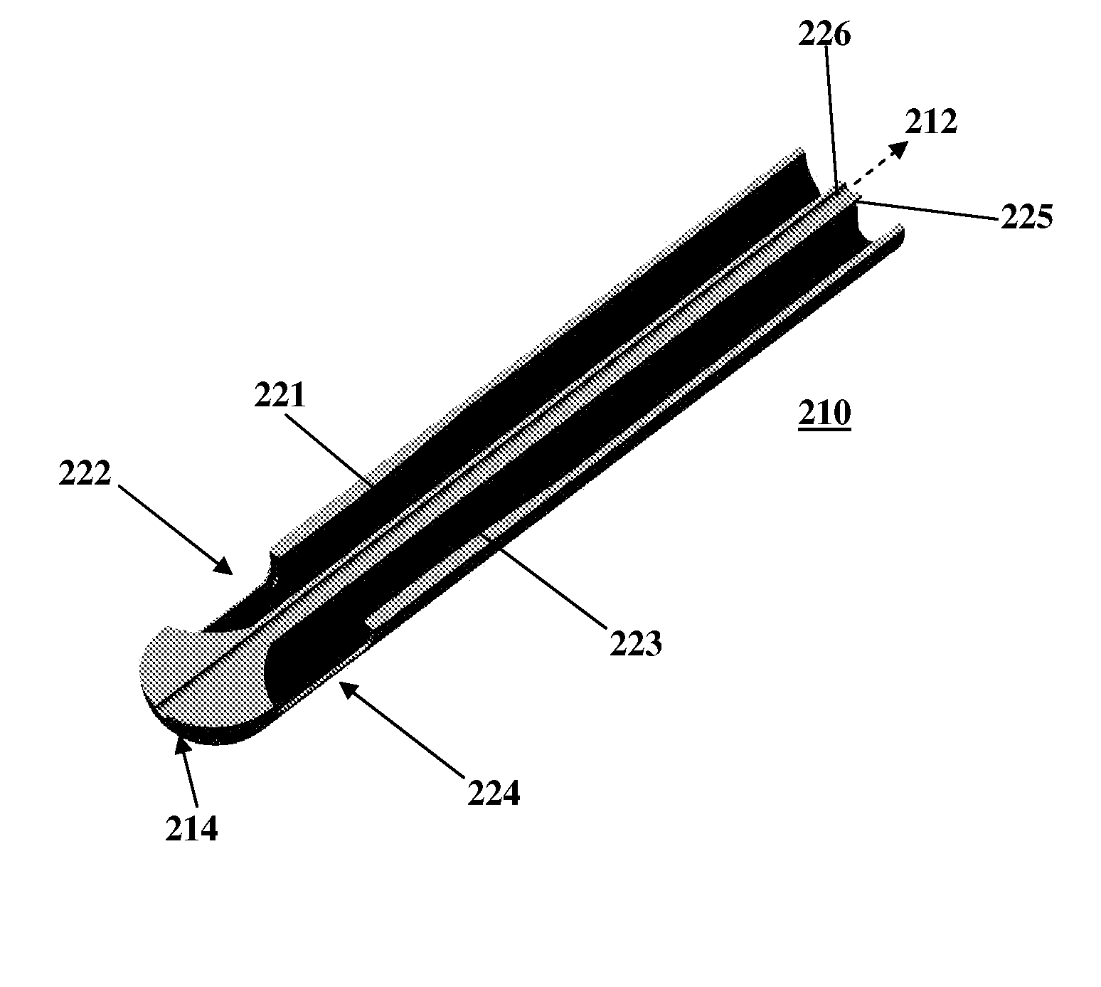
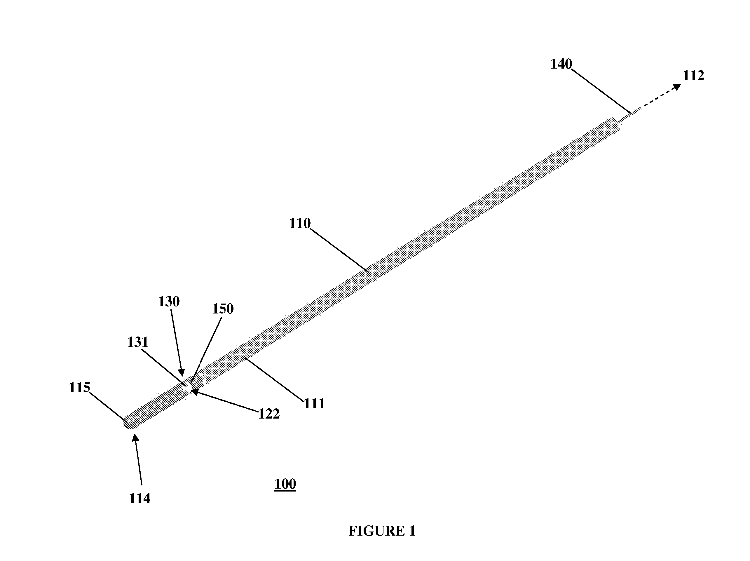
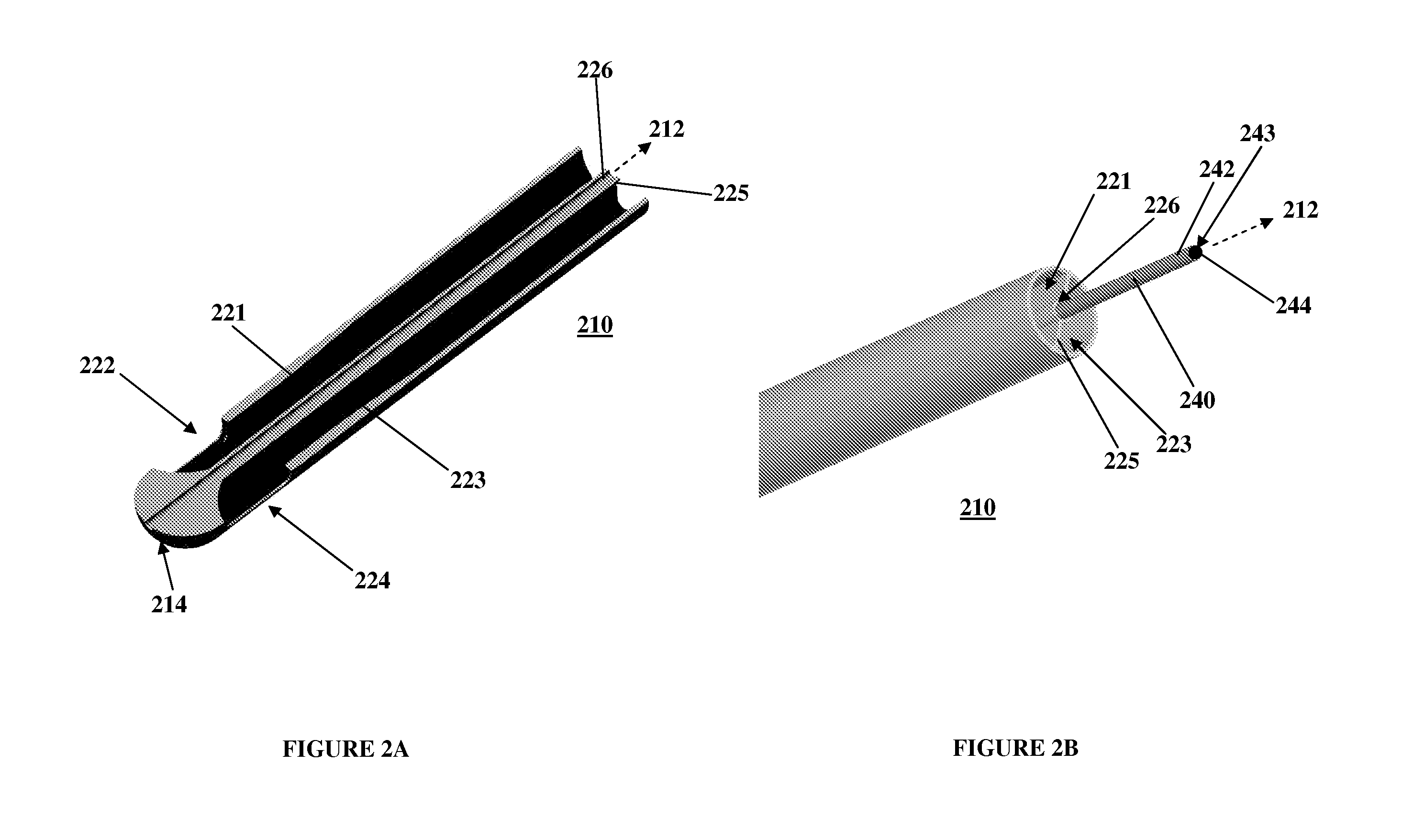
[0047] Referring to FIG. 1, an exemplary embodiment of the present invention is generally illustrated as a catheter 100. In particular, as described further below, the catheter 100 may be employed as a central venous catheter for hemodialysis. The catheter 100 has an elongate catheter body 110 which extends from a proximal end 112 to a distal end 114. The catheter 100 is generally flexible to permit positioning within a body passageway, such as a blood vessel. Flexibility, for instance, may be enhanced by incorporating multiple durometer elastomers or polymers within the parts of the catheter 100.

[0048] The catheter 100 has a lumen, or interior chamber, within the elongate catheter body 110. The interior chamber (not shown) acts to channel fluid between the proximal end 112 and the distal end 114. The interior chamber has a port, or chamber opening, 122 that passes through a body wall 111 of the catheter body 110. The chamber opening 122 allows the interior chamber to communicate w...


PUM


Abstract

A catheter device has an elongate body and a chamber positioned within the elongate body. The chamber has a chamber opening, and a barrier, such as a gate, moves over the chamber opening. The barrier moves between an uncovered position uncovering the chamber opening and a covered position covering the chamber opening. The catheter has at least one cutting edge by the chamber opening. In particular, the at least one cutting edge may be on the barrier, where the at least one cutting edge is guided over the chamber opening with movement of the barrier between the uncovered position and the covered position. The cutting edge cuts away a fibrin sheath blocking the chamber opening. The catheter may have multiple chambers connected by channels that allow the chambers to be flushed to prevent microbial colonization.

Description

CROSS REFERENCE TO RELATED APPLICATIONS [0001] This application claims priority to U.S. Provisional Application No. 60 / 735,257 filed Nov. 10, 2005, the contents of which are incorporated herein by reference.BACKGROUND OF THE INVENTION [0002] 1. Field of the Invention [0003] This invention relates generally to catheters, and more particularly, to a venous catheter adapted to prevent catheter failure caused by thrombus or fibrin formation at the distal end of the catheter and to prevent microbial infection. [0004] 2. Description of Related Art [0005] The use of cuffed tunneled central venous catheters has become widely accepted as a viable option for prolonged temporary vascular access as well as permanent vascular access for hemodialysis. It is estimated that 7 million central venous catheters (CVCs) will be inserted into patients annually in the United States. Unfortunately, the durability of central venous catheters is limited by catheter malfunction, primarily manifested by insuff...

Claims


Application Information

Patent Timeline
Patent Type & Authority Applications(United States)
IPC IPC(8): A61M37/00
CPCA61M25/003A61M25/0068A61M25/0074A61M2025/0037A61M25/0082A61M2025/0031A61M25/0075
Inventor RAVENSCROFT, ADRIANYANG, YIMINIGOE, MICHAEL
Owner PHASE ONE MEDICAL
Why Eureka
Try Eureka