Plasma processing apparatus

a plasma processing and apparatus technology, applied in the direction of welding apparatus, electric discharge tube, manufacturing tools, etc., can solve the problem of non-uniform radial characteristics of the process, and achieve the effect of improving the in-surface uniformity of the process characteristics

Inactive Publication Date: 2007-10-11
TOKYO ELECTRON LTD
View PDF2 Cites 27 Cited by
  • Summary
  • Abstract
  • Description
  • Claims
  • Application Information

AI Technical Summary

Benefits of technology

[0013]In accordance with still another embodiment of the present invention, there is provided a phase shifter for shifting a phase of the high frequency power passing through either the central power feeder or the peripheral power feeder. The phase shifter shifts a phase of the high frequency power flowing through, e.g., the peripheral power feeder, so that a phase difference is generated between the central branch current flowing in the central power feeder and the peripheral branch current flowing in the peripheral power feeder. By controlling a superposition state of the high frequency current in each port...

Problems solved by technology

As a result, process characte...

Method used


Image

  • Plasma processing apparatus
  • Plasma processing apparatus
  • Plasma processing apparatus

Examples


embodiment 1

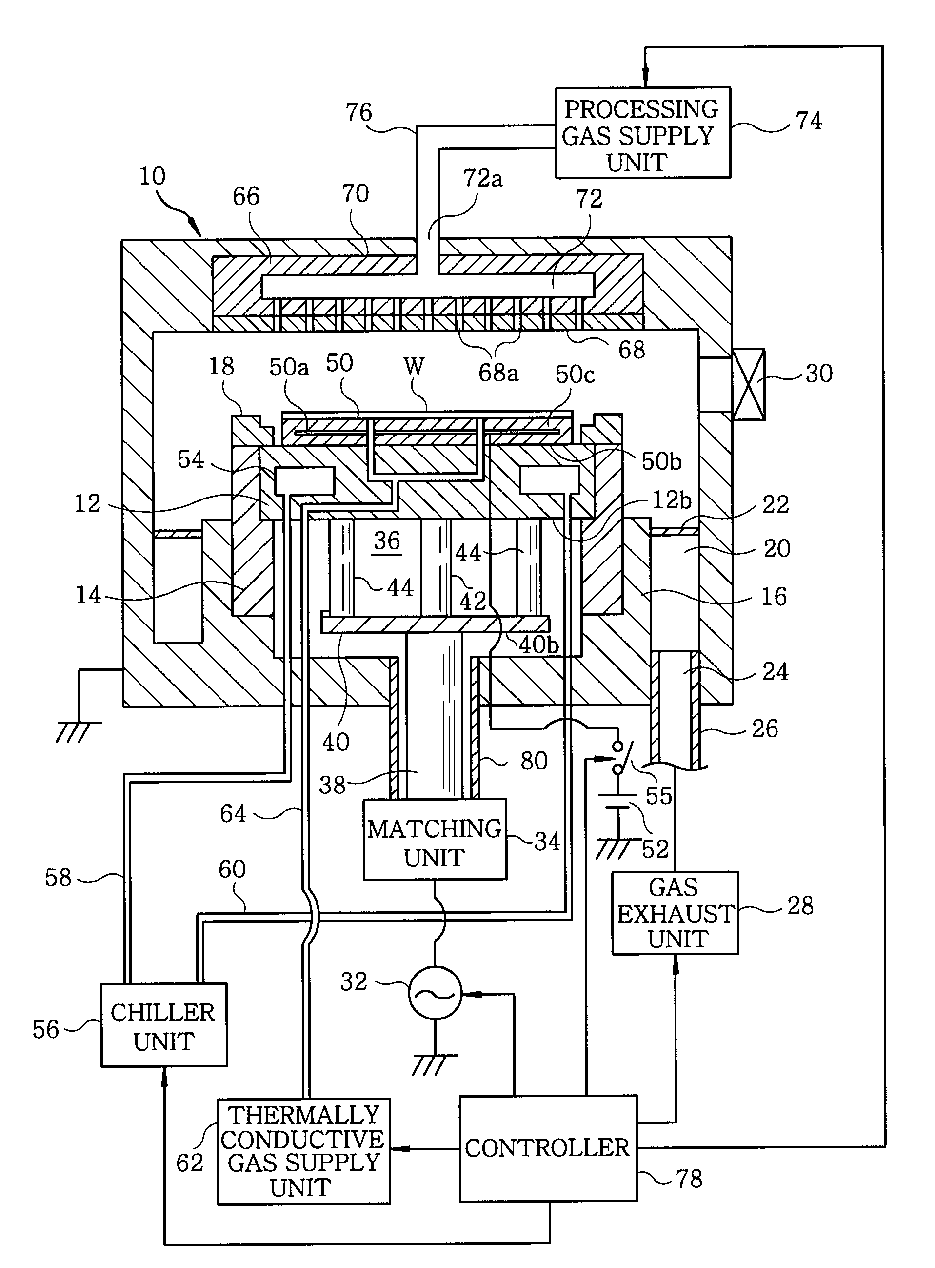
[0024]FIG. 1 shows a configuration of a plasma processing apparatus in accordance with a first embodiment of the present invention. The plasma processing apparatus is configured as a cathode-coupled parallel plate type plasma etching apparatus and has a cylindrical chamber (processing chamber) 10 made of metal such as aluminum or a stainless steel. The chamber 10 is frame grounded.

[0025]Horizontally disposed inside the chamber 10 is a circular plate shaped susceptor 12 serving as a lower electrode for mounting thereon a target substrate, e.g., a semiconductor wafer W. The susceptor 12 is supported by a cylindrical conductive supporting portion 16 elongated upward from a bottom portion of the chamber 10 via a cylindrical insulating maintaining portion 14 made of, e.g., aluminum. An annular focus ring 18 made of, e.g., quartz, is provided on a top surface of the cylindrical maintaining portion 14 to surround a top surface of the susceptor 12.

[0026]An annular exhaust passageway 20 is f...

embodiment 2

[0040]FIG. 6 shows a configuration of principal parts (high frequency power feed path) of a plasma processing apparatus in accordance with a second embodiment of the present invention. The plasma processing apparatus of the second embodiment is the same as the apparatus of the first embodiment except that a variable capacitor unit 81 and current measuring units 82 and 84 are attached to the high frequency power feed path 36. Therefore, like reference numerals will be given to like parts having substantially same configurations or functions.

[0041]As shown in FIG. 6, the variable capacitor unit 81 is provided between the power distribution plate 40 and the central power feeder 42 in the high frequency power feed path 36. The variable capacitor unit 81 includes therein a variable capacitor (for example, a vacuum variable capacitor), which is an actual electrically connected component between the power supply plate 40 and the central power feeder 42, and an actuator (e.g., a motor), whi...

embodiment 3

[0044]FIG. 7 illustrates a configuration of principal parts of a plasma etching apparatus in accordance with a third embodiment of the present invention. The third embodiment is equal to the first embodiment except that it has different high frequency power supply systems.

[0045]As described in FIG. 7, in this embodiment, the central power feeder 42 and the peripheral power feeders 44 have different systems in the high frequency power feed path from the high frequency power supply 32 to the susceptor 12. To be specific, a first power feed system 88 includes an output terminal of the high frequency power supply 32, a cable 86, a matching unit 34A, the central power feeder 42 and the susceptor 12. Meanwhile, a second power feed system 102 includes another output terminal of the high frequency power supply 32, a cable 90, a phase shifter 92, a cable 94, a matching unit 34B, a power feeder 96, a power feeder 98, an annular power supply plate 100, the peripheral power feeders 44 and the s...


PUM

PropertyMeasurementUnit
Frequencyaaaaaaaaaa
Capacitanceaaaaaaaaaa
Electric impedanceaaaaaaaaaa

Abstract

A plasma processing apparatus performs a desired plasma processing on a target substrate by using a plasma generated from a processing gas by forming a high frequency electric field in an evacuable processing chamber having an electrode. The plasma processing apparatus includes a high frequency power supply for outputting a high frequency power; and a central power feeder connected with a central portion of a rear surface of the electrode to supply the high frequency power from the high frequency power supply to the electrode. The plasma processing apparatus further includes a peripheral power feeder connected with a peripheral portion of the rear surface of the electrode in parallel with the central power feeder to supply the high frequency power from the high frequency power supply to the electrode.

Description

FIELD OF THE INVENTION[0001]The present invention relates to an apparatus for performing a plasma processing on a target substrate; and, more particularly, to a high frequency discharge plasma processing apparatus for generating a plasma by applying a high frequency power to an electrode.BACKGROUND OF THE INVENTION[0002]In a manufacturing process of a semiconductor device or an FPD (Flat Panel Display), a plasma is used for performing a microprocessing or a treatment such as etching, deposition, oxidation, sputtering or the like so that a reaction of a processing gas can be carried out under a relatively low temperature. In general, a plasma generation technique of a plasma processing apparatus is classified into two types: one using glow discharge or high frequency power and the other using microwaves.[0003]As disclosed in Japanese Patent Laid-open Application No. H6-283474 and U.S. Pat. No. 5,494,522, for example, the high frequency discharge plasma processing apparatus applies a ...

Claims


Application Information

Patent Timeline
IPC IPC(8): B23K9/00
CPCH01J37/32091H01J37/32174H01J37/32165
Inventor YAMAZAWA, YOHEI
Owner TOKYO ELECTRON LTD
Why Eureka
Try Eureka