
FM transmitter using switched capacitor filter

a capacitor filter and fm transmitter technology, applied in the field of fm transmitters, can solve the problems of increasing the number of components, difficult to be incorporated in an ic (integrated circuit), and so as to achieve the effect of reducing the circuit siz

Inactive Publication Date: 2007-10-11
ROHM CO LTD
View PDF4 Cites 5 Cited by
  • Summary
  • Abstract
  • Description
  • Claims
  • Application Information

AI Technical Summary

Benefits of technology

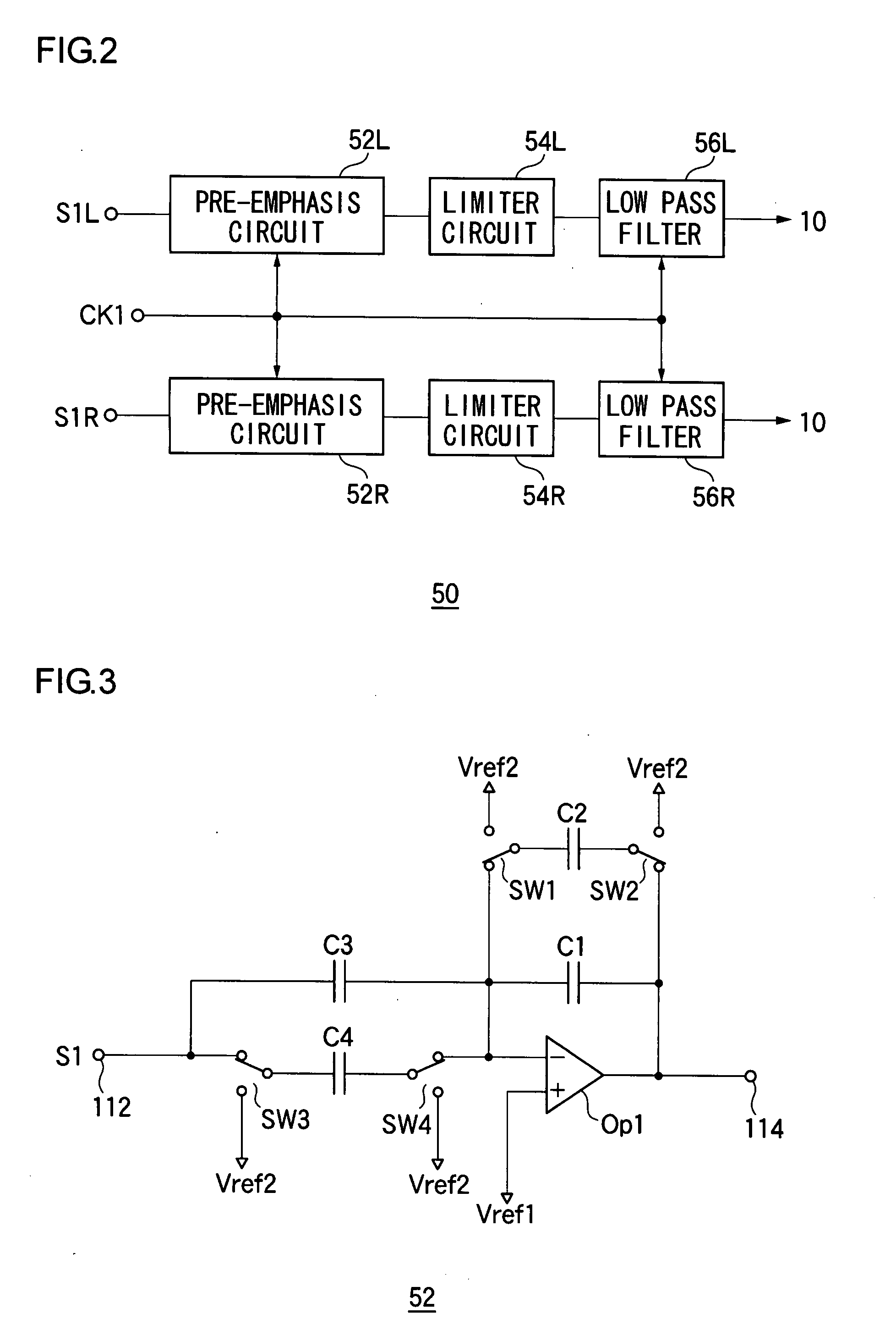
The present invention provides an FM transmitter with a reduced circuit size. The filter circuit is designed with a switched capacitor filter, which makes it possible to integrate the circuit onto a semiconductor substrate. The filter circuit can be configured with a low pass filter or a pre-emphasis circuit, and both can be integrated onto the substrate. The frequency modulator is designed with a direct modulation type including a PLL circuit, and the clock signal used for switching the switched capacitor filter can be the same as the reference clock signal of the PLL circuit. The invention also includes a compact electronic equipment that includes the FM transmitter and an antenna.

Problems solved by technology

Miniaturization of the circuit is a critical issue when incorporating the FM transmitter in the compact electronic equipments such as a portable telephone terminal.
Furthermore, the capacitance value of the capacitor becomes extremely large as the frequency band of the audio signal is being handled, and thus it becomes difficult to be incorporated in an IC (Integrated Circuit), which increases the number of components.
The increase in the number of components also inhibits mounting to the compact electronic equipment.

Method used


Image

  • FM transmitter using switched capacitor filter
  • FM transmitter using switched capacitor filter
  • FM transmitter using switched capacitor filter

Examples


Embodiment Construction

[0035] The invention will now be described based on preferred embodiments which do not intend to limit the scope of the present invention but exemplify the invention. All of the features and the combinations thereof described in the embodiment are not necessarily essential to the invention.

[0036]FIG. 1 is a circuit diagram showing a configuration of an FM transmitter 100 according to the embodiment of the present invention. In the subsequent figures, the same reference numerals are denoted for components which are same or equivalent to the already mentioned components, and the appropriate description thereof is not repeated. The FM transmitter 100 converts a stereo audio signal S1L, S1R (hereinafter referred to simply as input audio signal S1) including L channel and R channel input to an input terminal 102 to a stereo composite signal, frequency-modulates, and thereafter, amplifies the stereo composite signal and outputs the obtained signal from an output terminal 104. The FM tran...


PUM


Abstract

The FM transmitter converts an input audio signal to a stereo composite signal, frequency-modulates the stereo composite signal and outputs the obtained signal. A stereo modulator stereo-modulates the output signal of the filter circuit, and converts the signal to the stereo composite signal. A frequency modulator frequency-modulates based on the stereo composite signal output from the stereo modulator. The filter circuit includes a pre-emphasis circuit, a low pass filter and the like, for example. At least one part of the filter circuit, that is, the low pass filter or the pre-emphasis circuit is configured with a switched capacitor filter.

Description

BACKGROUND OF THE INVENTION [0001] 1. Field of the Invention [0002] The present invention relates to an FM transmitter for generating a stereo composite signal, frequency-modulating the stereo composite signal and outputting the obtained signal. [0003] 2. Description of the Related Art [0004] An FM transmitter for converting an audio signal to a stereo composite signal, frequency-modulating the stereo composite signal using a frequency modulator and outputting the obtained signal is known. Such FM transmitter is able to transmit the audio signal without using wirings such as RCA cable, and thus is used in transmitting signals between the CD changer of a car audio and the main head unit. Furthermore, hard disc audio equipments, memory audio equipments, portable telephone terminals having music reproducing function are significantly becoming widely used in recent years, and FM transmitter is used to reproduce musical data stored in such compact electronic equipments from a speaker of ...

Claims


Application Information

Patent Timeline
Patent Type & Authority Applications(United States)
IPC IPC(8): H04H5/00H03H19/00H04B1/04
CPCH04H20/48H04B1/04H04B1/03
Inventor SAGARA, TAKESHI
Owner ROHM CO LTD
Learn More