Blood flow imaging

a technology of flow and imaging, applied in the field of blood flow imaging, can solve the problems of decreased measurement accuracy, poor accuracy of motion estimation, and inability to guarantee the accuracy of time-series signals obtained by plural times

Active Publication Date: 2007-10-11
FUJIFILM HEALTHCARE CORP
View PDF15 Cites 11 Cited by
  • Summary
  • Abstract
  • Description
  • Claims
  • Application Information

AI Technical Summary

Benefits of technology

[0017]According to the blood-flow image display equipment of this invention, the blood flow measurement that is not affected by the motion of the object is possible, and the high-accuracy blood-flow distribution image containing a low-velocity blood flow that is close to a tissue motion in velocity can be displayed.

Problems solved by technology

However, since tissues inside an organism are always moving by influences of respiration and heart beat, there is no guarantee that time-series signals obtained by plural times of transmitting / receiving are reflection signals from the same area of the object.
However, since the frequency filtering processing loses information of low-velocity blood flows that are comparable with a motion of a tissue, there remains a problem of decreased measurement accuracy.
However, in order to obtain a blood flow image in which the motion is corrected using the RF signal in imaging a blood flow image, the method comes with the following problem.
This specification deteriorates spatial resolution in the depth direction, resulting in poor accuracy of motion estimation.
Therefore, accuracy in the lateral direction is also poor in estimating a motion from the blood flow image signal.
Even if the accuracy is sufficient, since the scanning line is coarse, information of positions corresponding to positions after deformation is lost; therefore, even if the conventionally known body motion correction method or a body motion correction method for a range that can be analogized therefrom is performed, a blood flow image imaging of a body-motion-correction integration type is hard to achieve.

Method used


Image

  • Blood flow imaging
  • Blood flow imaging
  • Blood flow imaging

Examples


first embodiment

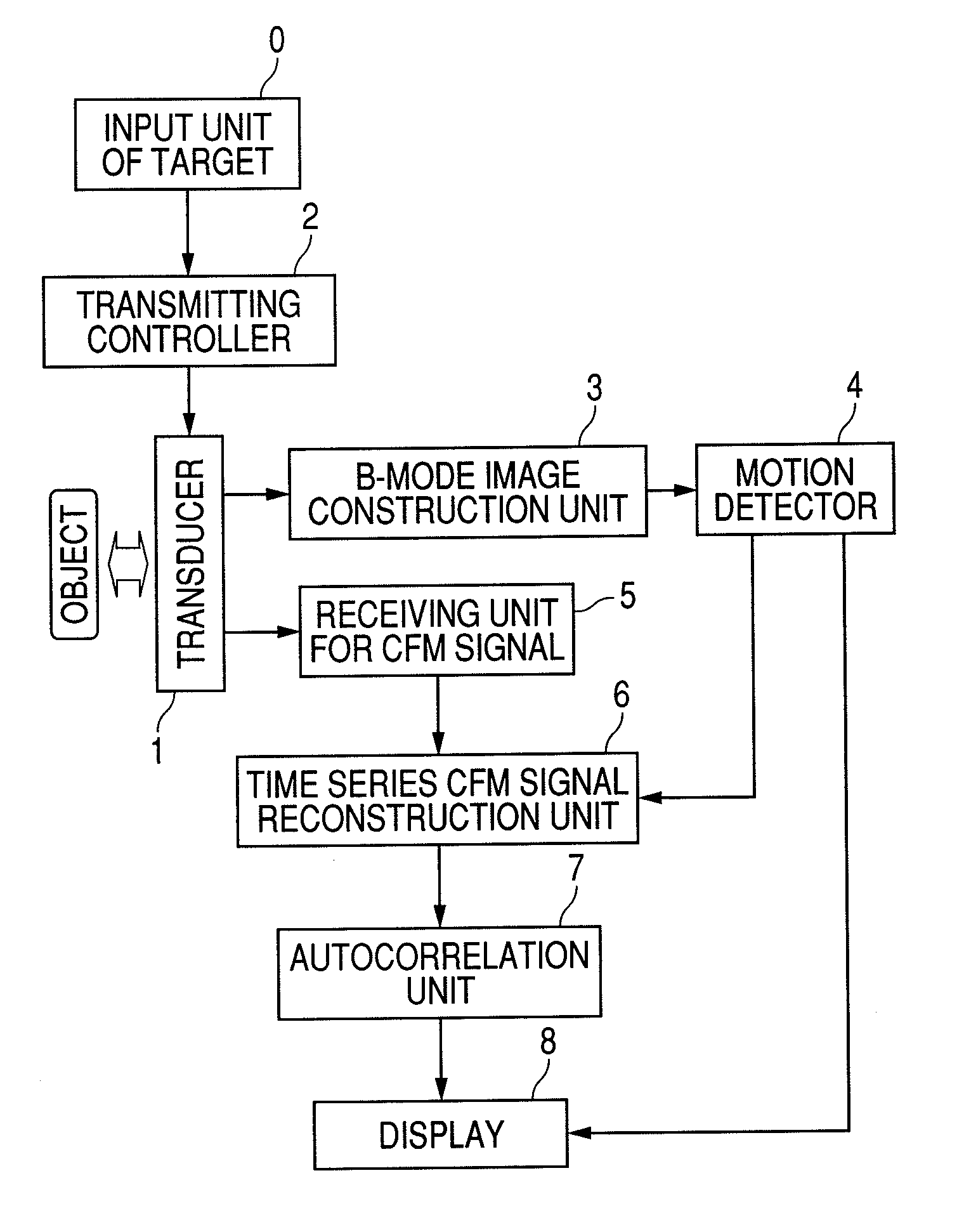
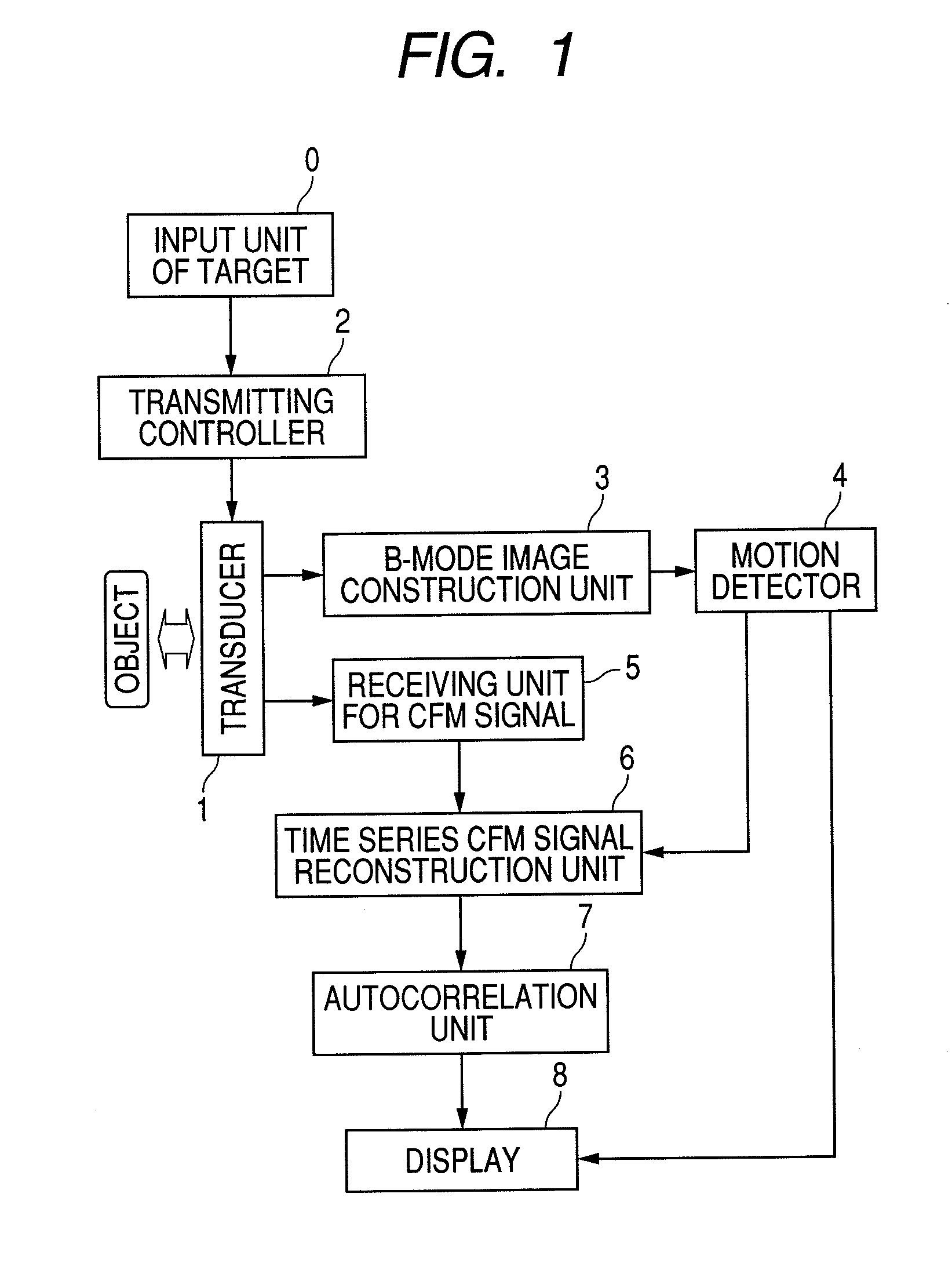
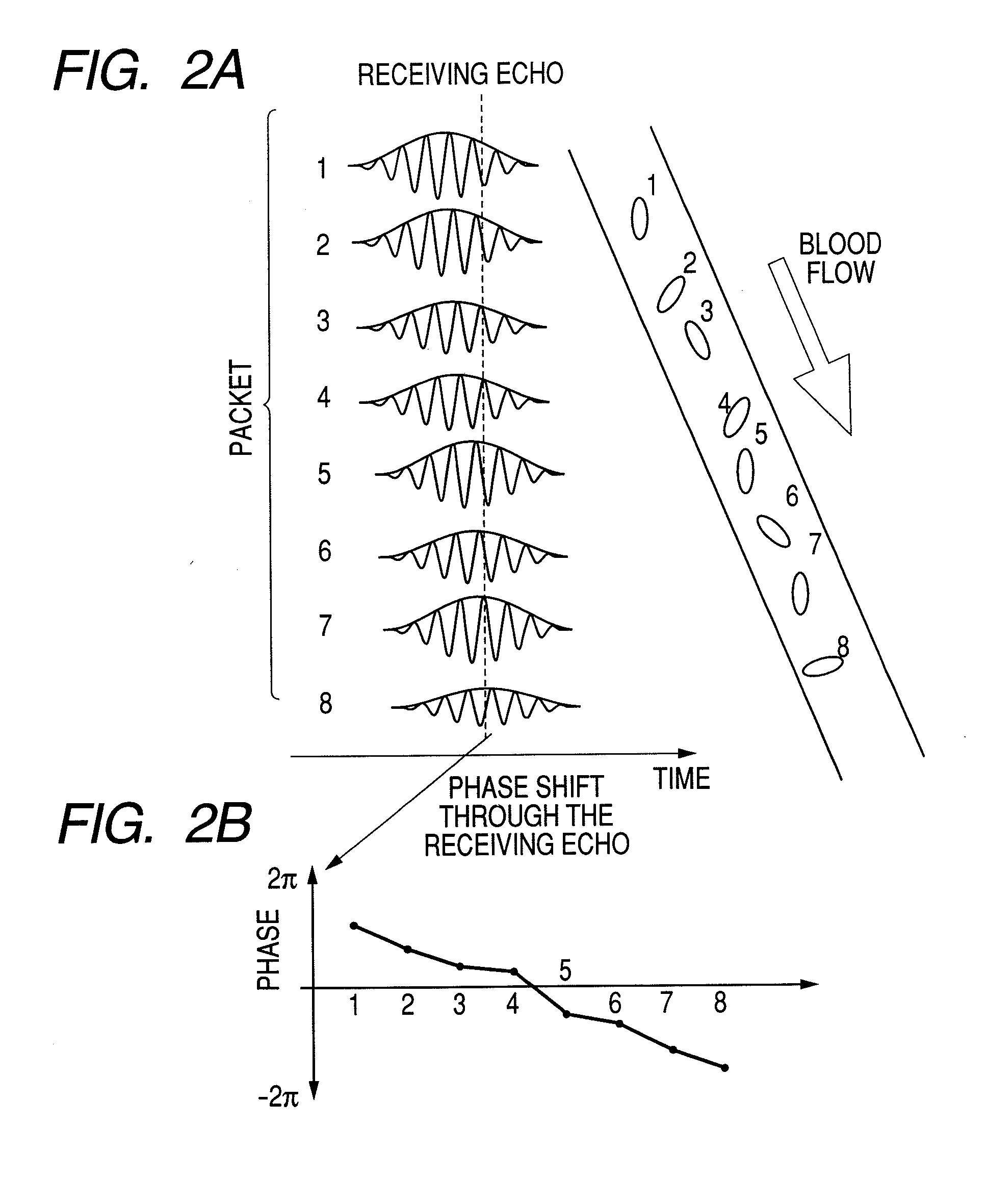
[0037]First, an imaging principle of CFM will be explained using FIG. 13. The right-hand side of the figure shows a motion of one blood cell at time 1 to time 8. In order to capture the motion of this blood cell, a signal is transmitted to and received from the same portion multiple times, as one set (in this example eight times), which is called packet wave transmitting / receiving. On the right-hand side of the figure, receiving wave echo signals in each packet when an ultrasonic wave is transmitted / received at time 1 to time 8. Since a distance to the object varies depending on a motion of the object, the receiving wave pulse signals shift on a temporal axis. As shown by a dotted lined in the figure, when viewing the pulse signals at a certain point on the temporal axis, the phase rotates in the packet, as shown by (1b) of FIG. 13. From the amounts of phase rotation, a motion velocity of the object at each position is estimated and imaged, which is called CFM imaging. An optimal re...

second embodiment

[0067]Hereafter, three-dimensional blood-flow image display equipment using the blood-flow image display equipment of the first embodiment will be described using the block diagram of FIG. 10.

[0068]Several structures of a transducer used to capture three-dimensional information of an object and several imaging methods are conceivable. In the case where the transducer 1 is a one-dimensional array, in order to capture three-dimensional information, it is necessary to make the transducer scan in the slice direction mechanically. To implement the scanning method, the operator may scan the transducer 1 manually or the transducer 1 may be scanned automatically by motor control. In the case where the transducer 1 is of a two-dimensional array, since an arbitrary imaging plane can be captured without mechanically moving the transducer, it is possible to easily capture three-dimensional information of the object by scanning the imaging plane in the slice direction automatically.

[0069]A const...

third embodiment

[0072]In the first embodiment, the result of motion estimation in the B-mode imaging is used to collect data that corresponds to the same area from pieces of CFM data having already been acquired. In this third embodiment, a raster position at which the next transmitting / receiving is done is corrected by using a result of motion estimation in the B-mode imaging, and accordingly a smaller motion is corrected. That is, by performing tracking to the motion, not by specifying a raster position to space, a raster that is associated with each tissue in an object organ is defined. This embodiment is effective especially in order to image a low-velocity blood flow in a peripheral blood vessel where the body motion and the velocity of the blood flow are of the same order. Since conventionally, a difference between the velocities was used to remove the body motion, imaging of a low-velocity blood flow was difficult. In this embodiment, motion estimation by B-mode imaging is performed between ...


PUM


Abstract

Blood-flow image display equipment for displaying a CFM image that is not affected by a motion of a tissue in an object area during capturing of images or is affected in a reduced manner. The blood-flow image display equipment has following components: a transmitting controller for controlling transmission triggers of a signal for B-mode and a signal for CFM based on a velocity of motion of an object; an ultrasonic transducer in which piezoelectric ultrasonic transducers each for transmitting/receiving an ultrasonic wave to/from the object are arranged in the form of an array; a B-mode image construction unit for constructing a B-mode image with received signals; a motion detector for measuring a motion vector of the object using the B-mode image; a receiving unit for CFM signal for receiving the signal for CFM from the ultrasonic transducer; a time-series signal storage unit for CFM that collects a CFM measurement region located in the same area of the object based on the motion vector measured by the motion detector and stores them in memory in time sequence; and an autocorrelation processing unit for performing autocorrelation processing on time-series CFM signals.

Description

CLAIM OF PRIORITY[0001]The present application claims priority from Japanese application JP 2006-044650 filed on Feb. 22, 2006, the content of which is whereby into this application.BACKGROUND OF THE INVENTION[0002]The present invention relates to equipment that measures a mean blood flow velocity of an object to be examined using plural ultrasonic signals that are transmitted / received by an ultrasonic transducer, corrects a motion of the object that is being measured using ultrasonic images when constructing a two-dimensional image representing a blood flow distribution, and displays a high-accuracy blood flow image from which an effect of the motion is removed.FIELD OF THE INVENTION[0003]Since the color flow mapping (CFM) of a blood flow using ultrasonic waves can image a distribution of blood vessels and hemodynamics noninvasively and in real time, it has become an indispensable technology in medical fields as a monitoring tool for diagnosis and treatment.[0004]The blood-flow mea...

Claims


Application Information

Patent Timeline
Patent Type & Authority Applications(United States)
IPC IPC(8): A61B8/00
CPCA61B8/06A61B8/5276A61B8/13
Inventor YOSHIKAWA, HIDEKIAZUMA, TAKASHI
Owner FUJIFILM HEALTHCARE CORP
Why Eureka
Try Eureka