

Ultrasonography apparatus
- Summary
- Abstract
- Description
- Claims
- Application Information
AI Technical Summary
Benefits of technology
Problems solved by technology
Method used
Image

Examples
first embodiment
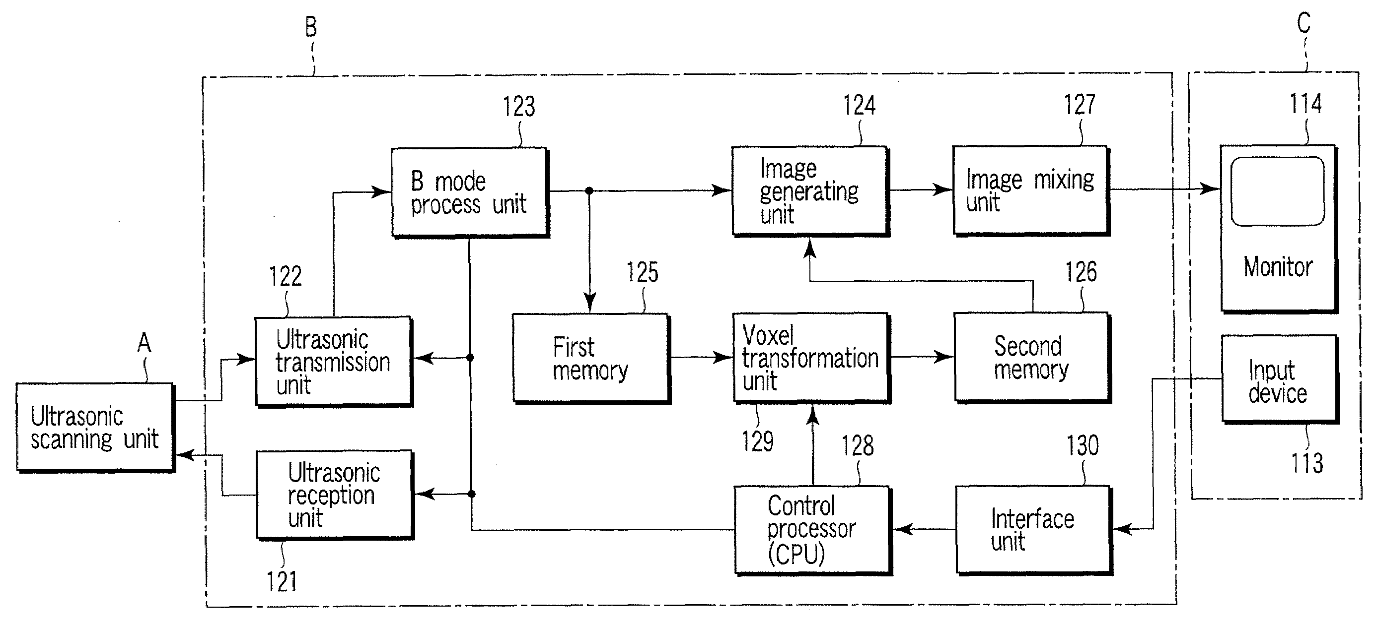
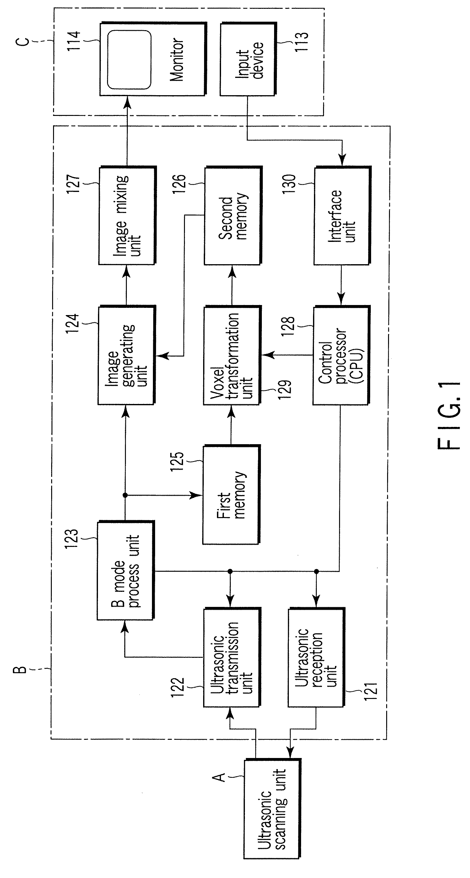
[0037]FIG. 1 is a block diagram showing the structure of an ultrasonography apparatus according to an embodiment of the invention. As shown in FIG. 1A, the ultrasonography apparatus includes an ultrasonography scanning unit A, an apparatus body B and a operation console C. The apparatus body B includes an ultrasonic transmission unit 121, an ultrasonic reception unit 122, a B mode process unit 123, an image generating unit 124, a first image memory 125, a second image memory 126, an image mixing unit 127, a control processor (CPU) 128, a voxel transformation unit 129, and an interface unit 130. In addition, the operation console C includes an input device 113 and a monitor 114.
[0038]The functions of the respective structural components will be described below.
[0039]The ultrasonic scanning unit A includes an ultrasonic array probe, a rotating mechanism which rotates the ultrasonic array probe while the ultrasonic transmission / reception surface of the ultrasonic array probe is being o...
example 1
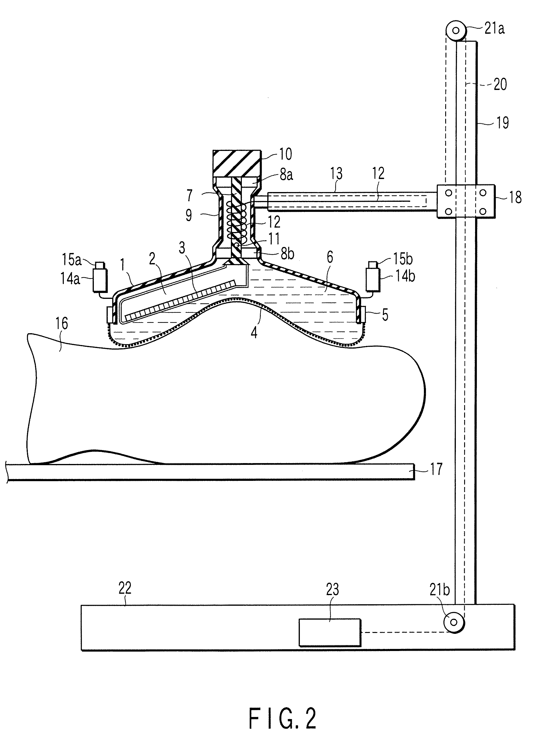
[0051]FIG. 2 shows an ultrasonic scanning unit A according to Example 1. A liquid sealing container, which contains hot water 6, is composed of a support cover 1, an ultrasonic transmission membrane 4 and a membrane fixing unit 5. An ultrasonic array probe 2 is disposed in the hot water 6. The liquid sealing container may be sealed completely or not. The ultrasonic array probe 2 is fixed to a rotational shaft 7 at a predetermined angle. The rotational shaft 7 is supported by bearings 8a and 8b. The rotational shaft 7 is rotated by a motor 10. Thereby, the ultrasonic array probe 2 is rotated in the liquid. The bearings 8a and 8b are fixed to an outer cylinder 9. The outer cylinder 9 is fixed to a distal end portion of a support arm 13 which is extendible. The other end portion of the support arm 13 is coupled to a support column 19 by means of a coupling unit 18. The support column 19 is secured to a support column base 22. Normally, hot water is used as the liquid. Although not show...
example 2
[0056]FIG. 3A shows an ultrasonic scanning unit A according to Example 2. Substantially the same liquid sealing container as that shown in FIG. 2 is disposed in an inverted fashion. The side surfaces of the support cover 1 are fixed to an outer frame 28 via a water supply / drain conduit 26. FIG. 2 depicts pipes 25a and 25b for circulating hot water at a fixed temperature of about 37° C. through the liquid sealing container, although the depiction of the pipes 25a and 25b is omitted in FIG. 2. Hot water at a fixed temperature circulates such that the hot water flows in through the intake pipe 25a, flows through the container, and flows out through the drain pipe 25b via a water port 24. The water port 24 is positioned above the liquid sealing container. Even if bubbles mix in the liquid sealing container, the bubbles are discharged from the water port 24 by the flow of the hot water.
[0057]The system according to Example 2 differs from the system according to Example 1 in that the wate...
PUM
 Abstract
Description
Claims
Application Information