Organic electroluminescent element, and manufacturing method thereof, as well as display device and exposure apparatus using the same

Inactive Publication Date: 2007-10-18
PANASONIC CORP
View PDF25 Cites 126 Cited by
  • Summary
  • Abstract
  • Description
  • Claims
  • Application Information

AI Technical Summary

Benefits of technology

[0018]The present invention has been made in view of the above circumstance, an object of which is to provide an organic electroluminescent element which is uniform in luminescence properties, stable in operation and excellent in life property.
[0019]The organic electroluminescent element of the present invention

Problems solved by technology

However, the element is unable to provide a sufficiently great luminescence intensity or is not adequate in durability for prolonged use, which is a problem to be improved.
To cause a phase separation means that where two polymer substances are loosely bound, they may be decomposed relatively easily, in other words, suggesting that when PEDT is driven in an organic electroluminescent element, it may be unstable, or as a result of the phase separation, compositions not contributing to the bonding, in particular, an ionic composition, may diffuse due to an electric field associated with electrification, thereb

Method used


Image

  • Organic electroluminescent element, and manufacturing method thereof, as well as display device and exposure apparatus using the same
  • Organic electroluminescent element, and manufacturing method thereof, as well as display device and exposure apparatus using the same
  • Organic electroluminescent element, and manufacturing method thereof, as well as display device and exposure apparatus using the same

Examples


Example

First Embodiment

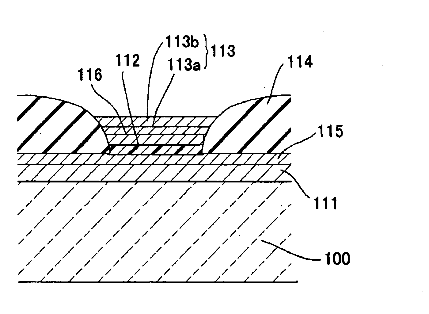
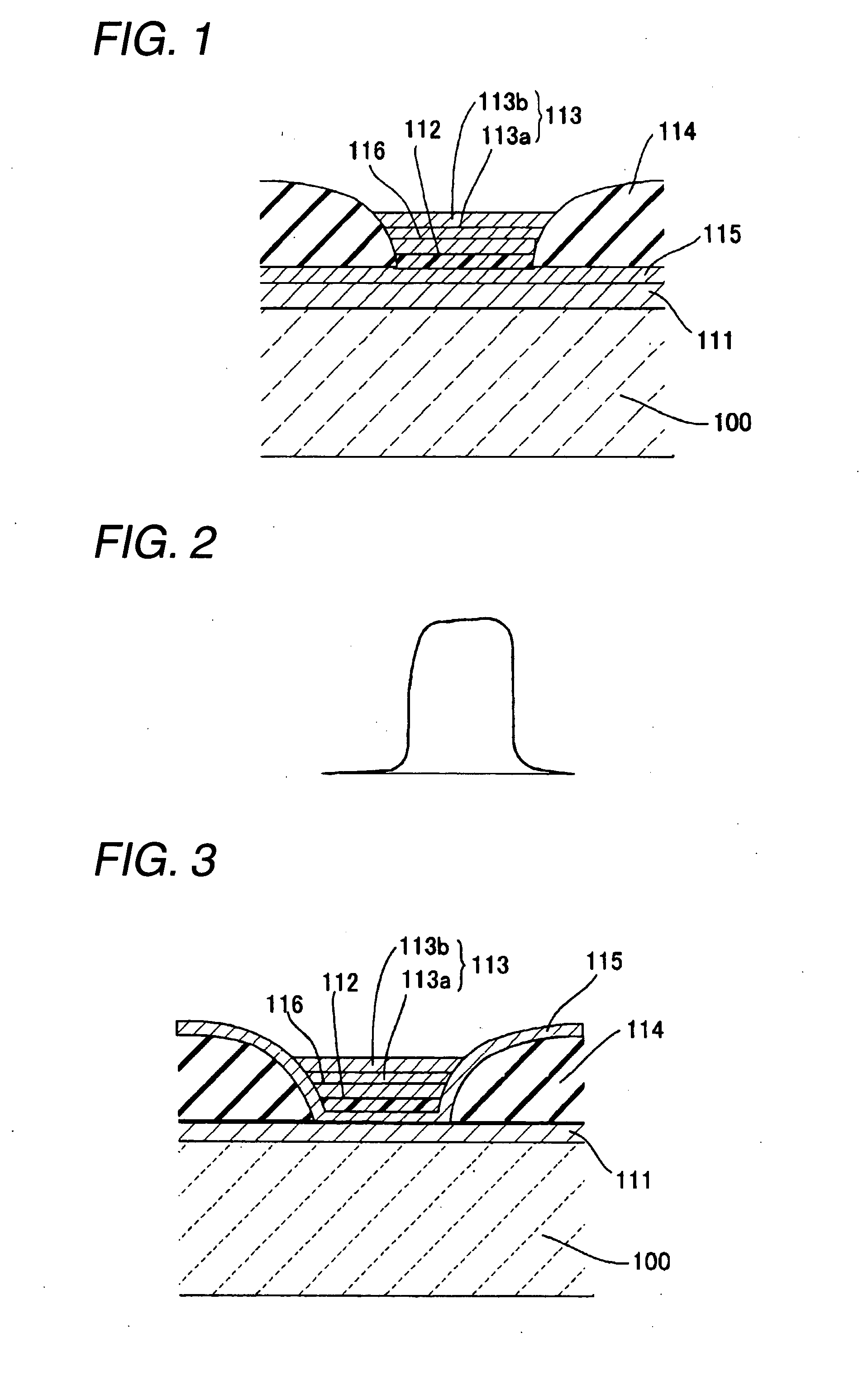
[0046]FIG. 1 is a block diagram illustrating an organic electroluminescent element of a first embodiment of the present invention.

[0047]As illustrated in FIG. 1, the organic electroluminescent element of the first embodiment is constituted with a substrate 100 based on a translucent glass, ITO (indium tin oxide) as a positive electrode 111 formed on the substrate 100, a transition metal oxide thin film (molybdenum oxide layer) as a charge-injection layer 115 additionally formed on the upper layer thereof, a luminescent layer 112 composed of a polymer material, a transition metal oxide thin film (molybdenum oxide layer) as a buffer layer 116, an intermediate layer 113a composed of Ba, Ca and the like, and an electrode layer 113b formed with a metal material such as Ag, Al, Mg or In (the intermediate layer 113a and the electrode layer 113b are collectively referred to as a negative electrode 113).

[0048]As described above, the organic electroluminescent element of the f...

Example

Second Embodiment

[0237]FIG. 15 is a sectional view showing a constitution of an organic electroluminescent element used in an exposure apparatus of an image forming device of a second embodiment of the present invention.

[0238]In the second embodiment, a detailed description will be made for the thickness of a transition metal oxide as the charge-injection layer 115 described in the first embodiment and a specific resistance value.

[0239]An electroluminescent element of the second embodiment is provided with a positive electrode 111 composed of ITO, a negative electrode 113 constituted, for example, with a metal and a functional layer formed between these electrodes on a translucent substrate 100. These functional layers are provided with a luminescent layer 112, that is, a luminescence function at least composed of an organic semiconductor polymer layer.

[0240]It is also provided with a transition metal oxide layer (specifically, 40 nm-thick molybdenum oxide layer) as the charge-injec...

Example

Third Embodiment

[0267]Hereinafter, a description will be given of a third embodiment with reference to drawings.

[0268]FIG. 16 is a sectional view showing an organic electroluminescent element of the third embodiment of the present invention. This electroluminescent element is provided with a positive electrode 111 composed of an ITO layer as a first electrode, a negative electrode 113 as a second electrode and a functional layer formed between these electrodes on a translucent substrate 100, in which the functional layer is provided with a luminescent layer 112, that is, a layer having the luminescence function composed of an organic semiconductor polymer layer, a 40 nm-thick transition metal oxide layer as the charge-injection layer 115 formed between the positive electrode 111 and the luminescent layer 112 (molybdenum oxide layer, hereinafter, referred to as transition metal oxide layer 115), a pixel restricting layer 114 composed of a 50 nm-thick silicon nitride film on the upper...


PUM


Abstract

To provide an organic electroluminescent element having uniform luminescence properties stable in operation and excellent in life property, an organic electroluminescent element in which a luminescent layer is provided between a positive electrode and a negative electrode, wherein a buffer layer constituted with a transition metal oxide (for example, molybdenum oxide) is provided between the negative electrode and the luminescent layer.

Description

BACKGROUND OF THE INVENTION[0001]1. Field of the Invention[0002]The present invention relates to an organic electroluminescent element and the method thereof, and furthermore, to a display device such as a display screen of a cellular phone and an exposure apparatus for an image forming device in which the organic electroluminescent element is used.[0003]2. Description of the Related Art[0004]An organic electroluminescent element is a light emitting device which utilizes an electroluminescence phenomenon of solid fluorescent materials and commercially available as a small-sized display screen in some cases.[0005]In particular, a so-called polymer organic electroluminescent element in which a polymer material is used as a luminescent material is available as a film according to wet coating methods such as a spin coating method, an ink jet method, a flood printing method, a gap coating method, a spray method, an LB method, and a printing method by using a solution in which a material ...

Claims


Application Information

Patent Timeline
IPC IPC(8): H05B33/26H01L51/50
CPCH01L51/5092H01L51/5088H10K50/171H10K50/17
Inventor SAKANOUE, KEIHAMANO, TAKAFUMIYAMAMOTO, SHINYAMATSUO, NAOTO
Owner PANASONIC CORP
Why Eureka
Try Eureka