Satellite communication system employing a combination of time division multiplexing and non-orthogonal pseudorandom noise codes and time slots

a satellite communication system and time slot technology, applied in the field of satellite communication systems, can solve the problems of cellular phone subscribers exceeding one million, crowded airwaves, and inability to meet the needs of the public,

a satellite communication system and time slot technology, applied in the field of satellite communication systems, can solve the problems of cellular phone subscribers exceeding one million, crowded airwaves, and inability to meet the needs of the public,

US20070243822A1Active Publication Date: 2007-10-18GLOBALSTAR INC

Image

  • Satellite communication system employing a combination of time division multiplexing and non-orthogonal pseudorandom noise codes and time slots
  • Satellite communication system employing a combination of time division multiplexing and non-orthogonal pseudorandom noise codes and time slots
  • Satellite communication system employing a combination of time division multiplexing and non-orthogonal pseudorandom noise codes and time slots

Examples


Embodiment Construction

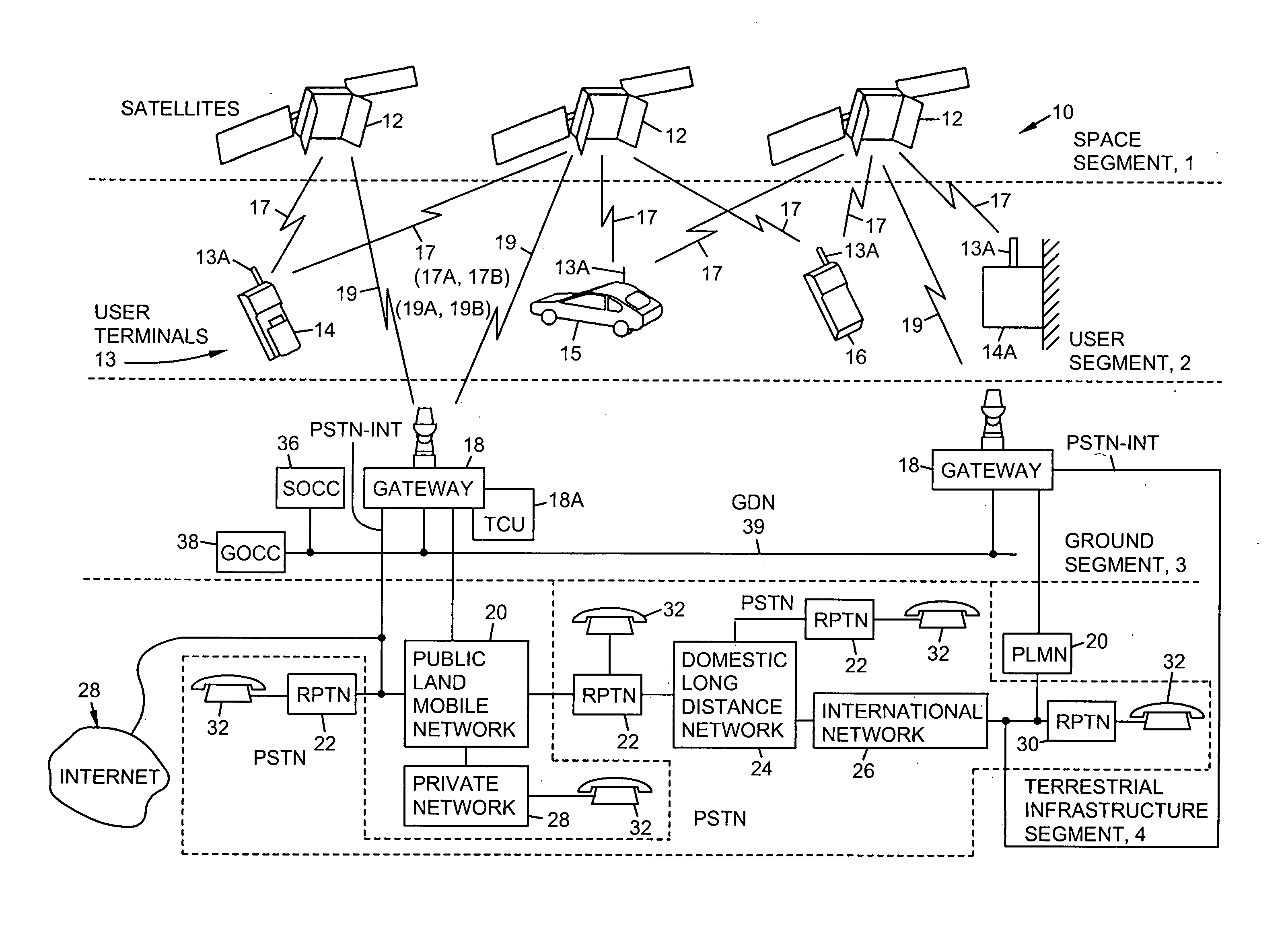
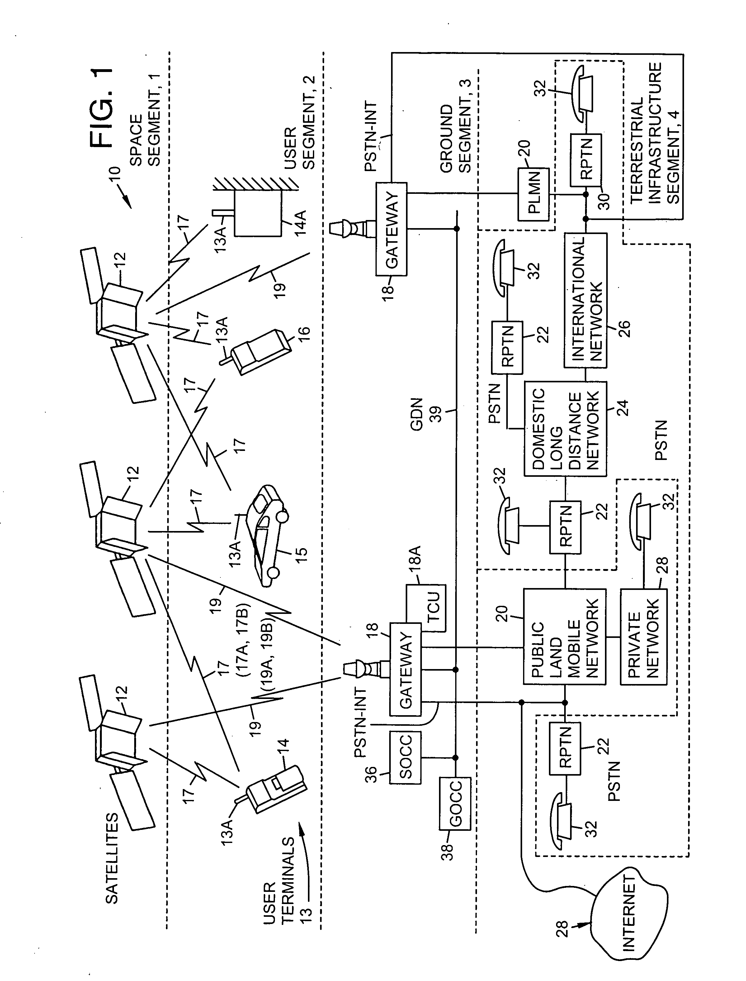
[0085]FIG. 1 illustrates a presently preferred embodiment of a satellite communication system 10 that is suitable for use with the presently preferred embodiment of this invention. Before describing this invention in detail, a description will first be made of the communication system 10 so that a more complete understanding may be had of the present invention.

[0086] The communication system 10 may be conceptually sub-divided into a plurality of segments 1, 2, 3 and 4. Segment 1 is referred to herein as a space segment, segment 2 as a user segment, segment 3 as a ground (terrestrial) segment, and segment 4 as a terrestrial system infrastructure segment; e.g., a telephone infrastructure.

[0087] In the presently preferred embodiment of this invention there are a total of 48 satellites in, by example, a 1414 km Low Earth Orbit (LEO). The satellites 12 are distributed in eight orbital planes with six equally-spaced satellites per plane (Walker constellation). The orbital planes are inc...


PUM


Abstract

An improved satellite communication system is provided comprising at least one satellite wherein each satellite provides multiple beams, a plurality of UTs, and at least one gateway connected to a PSTN and communicating with said at least one UT or with a constellation, wherein each of the UTs within a given frequency band is distinguished from another of the UTs employing a combination of TDM and NOPN codes and time slots.

Description

I. FIELD OF THE INVENTION [0001] The present invention relates to cellular telephone systems. More specifically, the present invention relates to new and improved systems and methods for communicating information in mobile cellular telephone systems or satellite mobile telephone systems employing spread spectrum communication signals. II. BACKGROUND OF THE INVENTION [0002] Historically, the telephone, which comes from the Greek word ‘tele’, meaning from afar, and ‘phone’, meaning voice or voice sound, is said to have been invented on Mar. 10, 1876 in Boston, Mass. by Alexander Graham Bell. The principle of the telephone was conceived as early as 1874 combining electricity and voice which led to Bell's actual invention of the telephone in 1876. [0003] U.S. Pat. No. 174,465 issued Mar. 3, 1876 for improvements in telegraphy is now considered to be the most valuable patent ever issued. [0004] Telstar, the world's first international communications satellite, years later was placed into...

Claims


Application Information

Patent Timeline
18 Oct 2007
Publication
US20070243822A1
IPC
H04B7/185
CPC
H04B7/2041; H04J3/10; H04B7/212; H04B7/204; H04W72/0446
Inventors
MONTE, PAUL A.; GALLAGHER, VIJAYA