Image diagnostic system and apparatus, and processing method therefor

a diagnostic system and image technology, applied in tomography, applications, catheters, etc., can solve the problems of difficult to achieve complete synchronization between the rotational speed of the radial scan motor and the rotational speed of the motor, and achieve good quality

Active Publication Date: 2007-10-18
TERUMO KK
View PDF4 Cites 26 Cited by
  • Summary
  • Abstract
  • Description
  • Claims
  • Application Information

AI Technical Summary

Benefits of technology

[0012]A tomographic image of good quality can be constructed even when synchronization is not achieved between the rotation cycle of the probe in radial scanning and the cycle of acquisition of as much as one frame of signals in line units from the probe in the image diagnostic system.

Problems solved by technology

Therefore, it is difficult to achieve complete synchronization between the rotational speed of the radial scan motor and the cycle of transmission / reception of signals at the probe.

Method used


Image

  • Image diagnostic system and apparatus, and processing method therefor
  • Image diagnostic system and apparatus, and processing method therefor
  • Image diagnostic system and apparatus, and processing method therefor

Examples


first embodiment

1. General Overall Construction of IVUS Imaging System

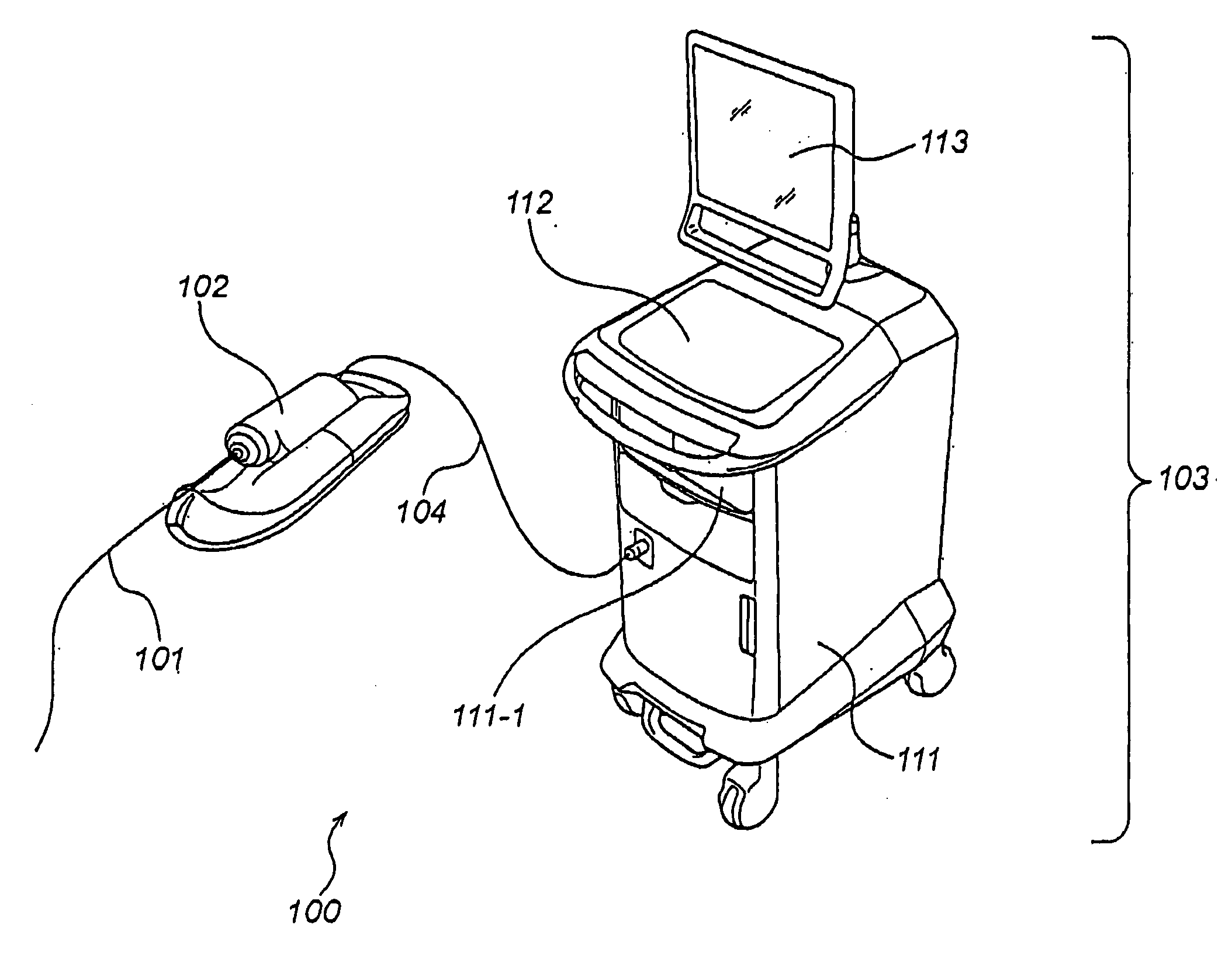
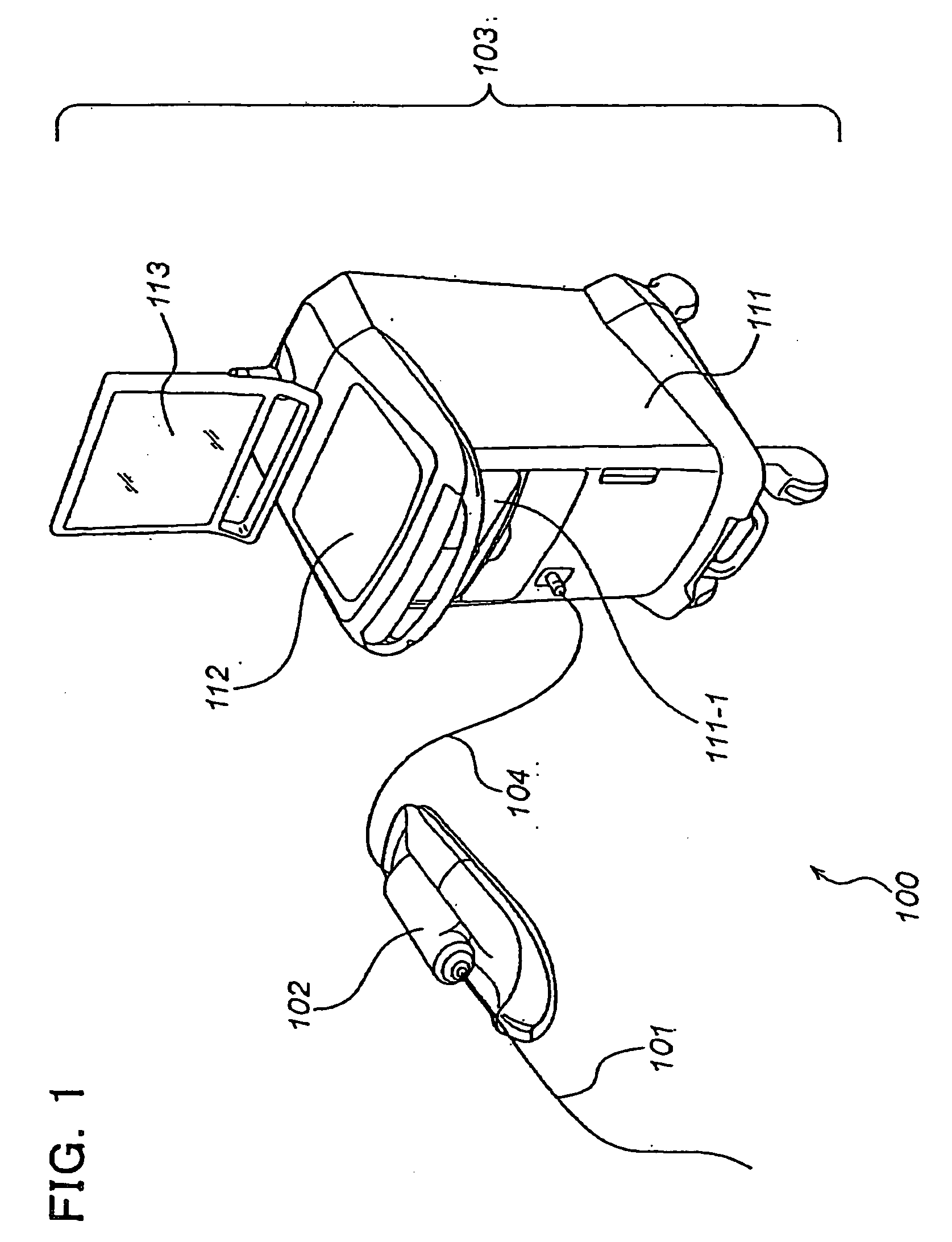
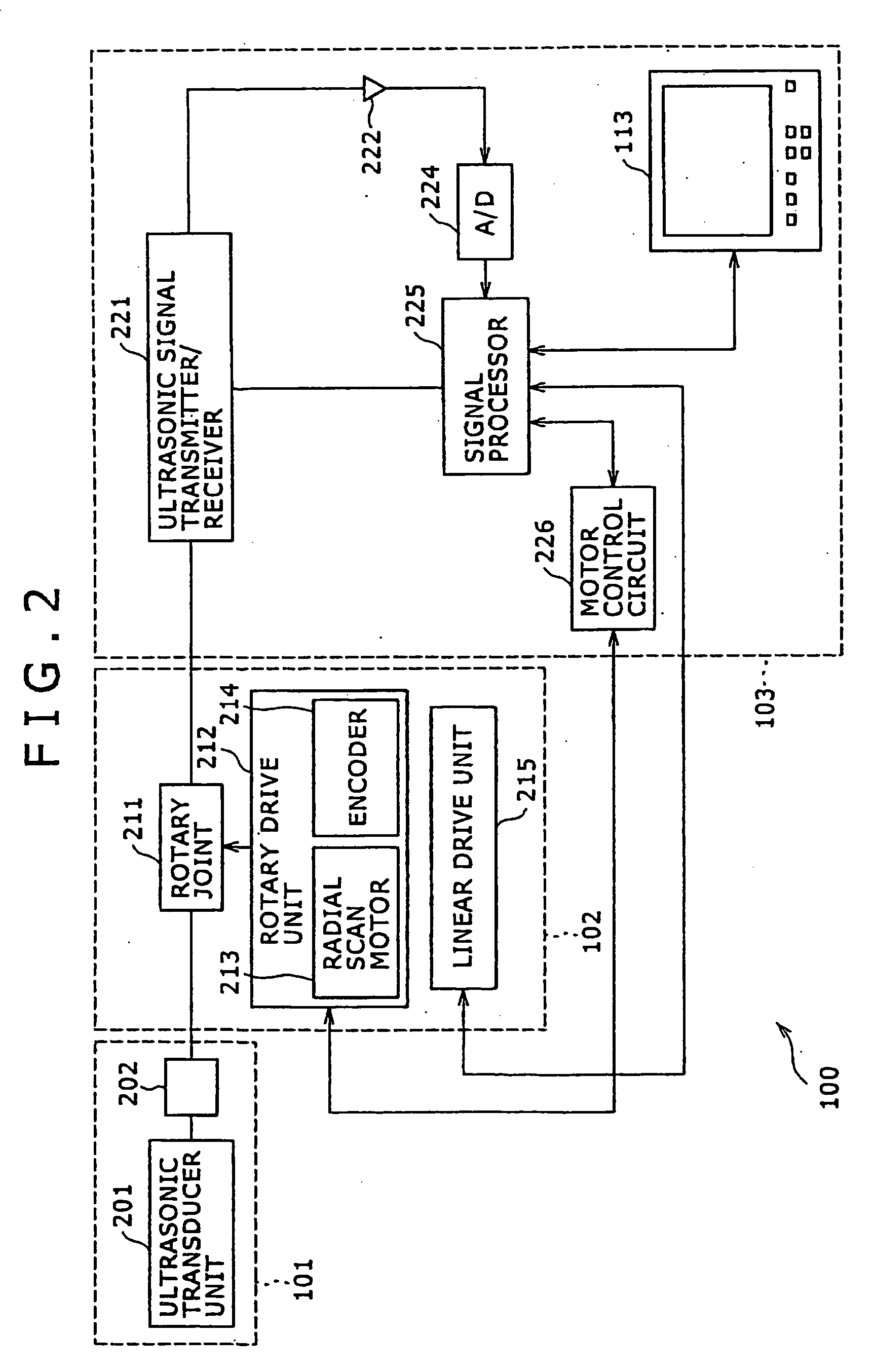
[0035]Referring to FIG. 1, an intravascular ultrasound (IVUS) imaging system (i.e., image diagnostic system) 100 according to one illustrated and disclosed embodiment includes a catheter section (i.e., probe) 101, a scanner & pull-back unit 102 and an operation control system 103. The scanner & pull-back unit 102 and the operation control system 103 are connected together via a signal line 104 and compose an image diagnostic apparatus.

[0036]The catheter section101 is adapted to be inserted directly into a blood vessel to measure internal conditions of the blood vessel by way of an ultrasonic transducer 401b which is shown in FIG. 4. The scanner & pull-back unit 102 controls movements of the ultrasonic transducer 401b within the catheter section 101.

[0037]The operation control system 103 operates to input various preset values upon performing an intravascular ultrasound diagnosis and to also process data acquired by a measurement ...

second embodiment

[0089]The description above describes about the processing at the A / D converter and the signal processor in an IVUS imaging system when the rotation cycle for radial scanning by the ultrasonic transducer and the transmission / reception cycle of ultrasonic signals at the probe are out of synchronization. However, the disclosure here is not specifically limited to IVUS imaging systems, but rather has useful application to other image diagnostic systems. The following describes application of the disclosure here to an optical coherence tomography (OCT) imaging system.

1. Measurement Principle of OCT Imaging System

[0090]The measurement principle of the OCT imaging system will first be briefly described. Because light is electromagnetic radiation, it generally has the property that beams of light interfere with each other when they are superimposed. The interference property that defines whether light interferes readily or hardly is called “coherence”, and in general OCT imaging systems, l...

third embodiment

[0140]The above-described second embodiment describes application of the disclosed subject matter to the OCT imaging system. However, the present invention is not limited specifically to OCT imaging systems as it can also be applied to OCT imaging systems making use of a wavelength swept light source. A description will hereinafter be made about applying the disclosure here to an OCT imaging system making use of a wavelength swept light source.

1. Measurement Principle of OCT Imaging System Making Use of a Wavelength Swept Light Source

[0141]Initially, a brief description is set forth of the measurement principle of the OCT imaging system making use of a wavelength swept light source. The OCT imaging system making use of a wavelength swept light source and the OCT imaging system described above as the second embodiment are basically the same in measurement principle as shown inFIGS. 10 and 11 in that they make use of optical interference. Accordingly, the description which follows pri...


PUM


Abstract

An image diagnostic system controls a probe to perform radial scanning within a body cavity produces data based on signals received by the probe to construct and display a tomographic image of the body cavity and surrounding biotissue. The system includes a generation unit, a selection unit and a conversion unit. The generation unit generates and outputs synchronization signals in synchronization with a timing of acquisition cycles of line units of the signals and generated at a higher frequency than output signals outputted corresponding to rotational angles of the probe upon performing the scanning. The selection unit successively receives the output signals, and selects and outputs first ones of the synchronization signals as received subsequent to the receptions of the output signals. Responsive to successive inputs of the synchronization signals selected by the selection unit, the conversion unit converts the reflected signals into digital signals and outputs the digital signals.

Description

TECHNICAL FIELD[0001]This invention generally relates to an image diagnostic system and apparatus, and a processing method therefor.BACKGROUND OF THE INVENTION[0002]Image diagnostic systems have been used for diagnosing arteriosclerosis, for preoperative diagnosis upon coronary intervention by a high-performance catheter such as a dilatation catheter (i.e., balloon catheter) or stent, and for assessing postoperative results.[0003]Examples of these image diagnostic systems include intravascular ultrasound (IVUS) imaging systems. In general, the intravascular ultrasound imaging system is constructed to control an ultrasonic transducer to perform radial scanning within a blood vessel, to receive a reflected wave(s) (ultrasound echoes) reflected by biotissue (e.g. the blood vessel wall) by the same ultrasonic transducer, to subject the reflected waves to processing such as amplification and detection, and then to construct and display a tomographic image of the blood vessel on the basis...

Claims


Application Information

Patent Timeline
Patent Type & Authority Applications(United States)
IPC IPC(8): A61B8/00
CPCA61B5/0066A61B5/0086A61B8/4461A61B8/12A61B5/6852
Inventor HIROTA, KAZUHIRO
Owner TERUMO KK
Why Eureka
Try Eureka