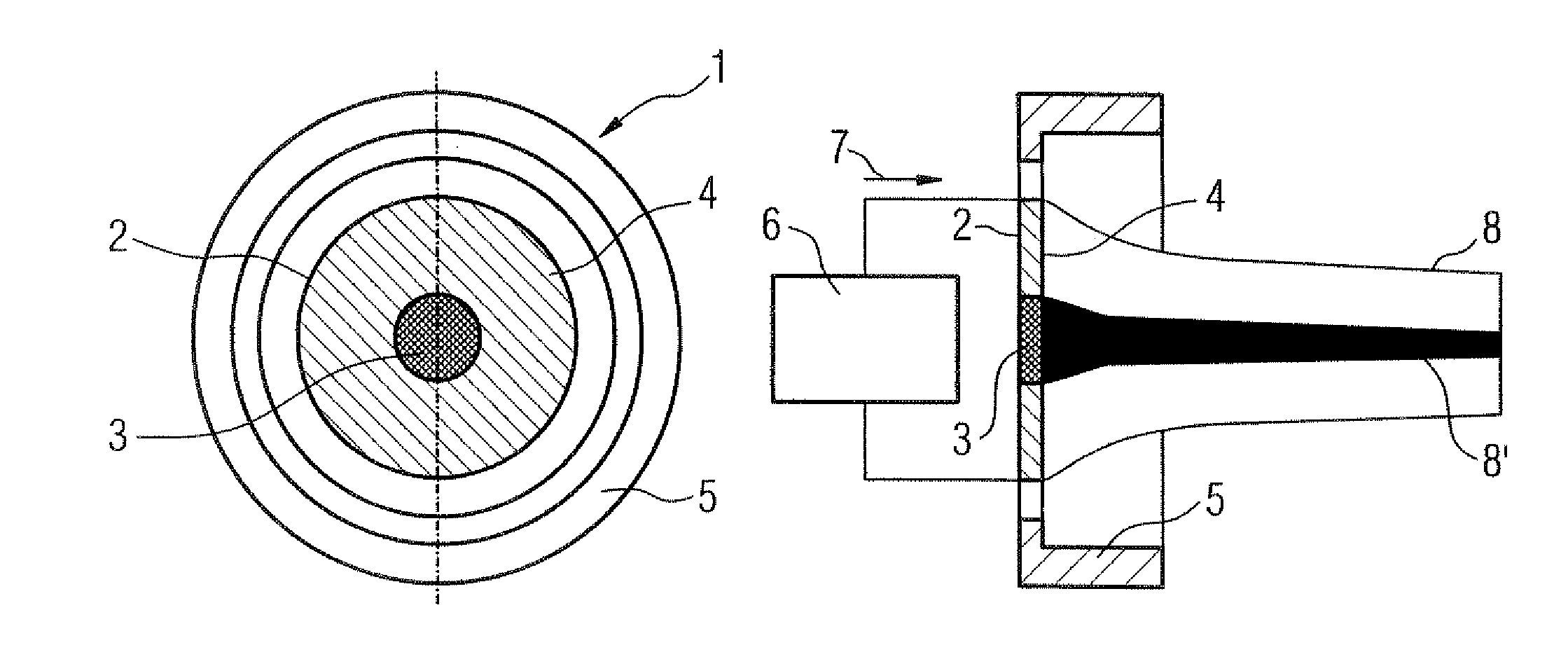
[0014]This object is achieved according to the invention by an emitter arrangement having a structure that, in operation, causes the
electron density of the emitted electrons to be lower in the
central region of the emitter plate than in a region adjoining the central region. “
Electron density,” as used herein is the number of electrons emitted per time and area unit. A broadening of the electron beam due to the repulsion of the electrons among one another is hereby countered, particularly given a very
high electron density. Due to the very high speed and the very
high momentum of the electrons, this broadening of the electron beam can only be partially compensated by focusing elements. A reduction of the
electron density in the central region of the emitter plate leads to the situation that the expansion of the electron beam is lower in comparison to a conventional emitter plate. A
field strength of smaller size thus can be achieved at the
anode location with the same focusing device. Improvements in the
image quality thus can be achieved, particularly in high-resolution imaging by means of x-
ray radiation. In the medical field, a higher
image quality means that tissue structures can be better resolved and a
medical diagnosis can thus be generated more precisely and exactly.
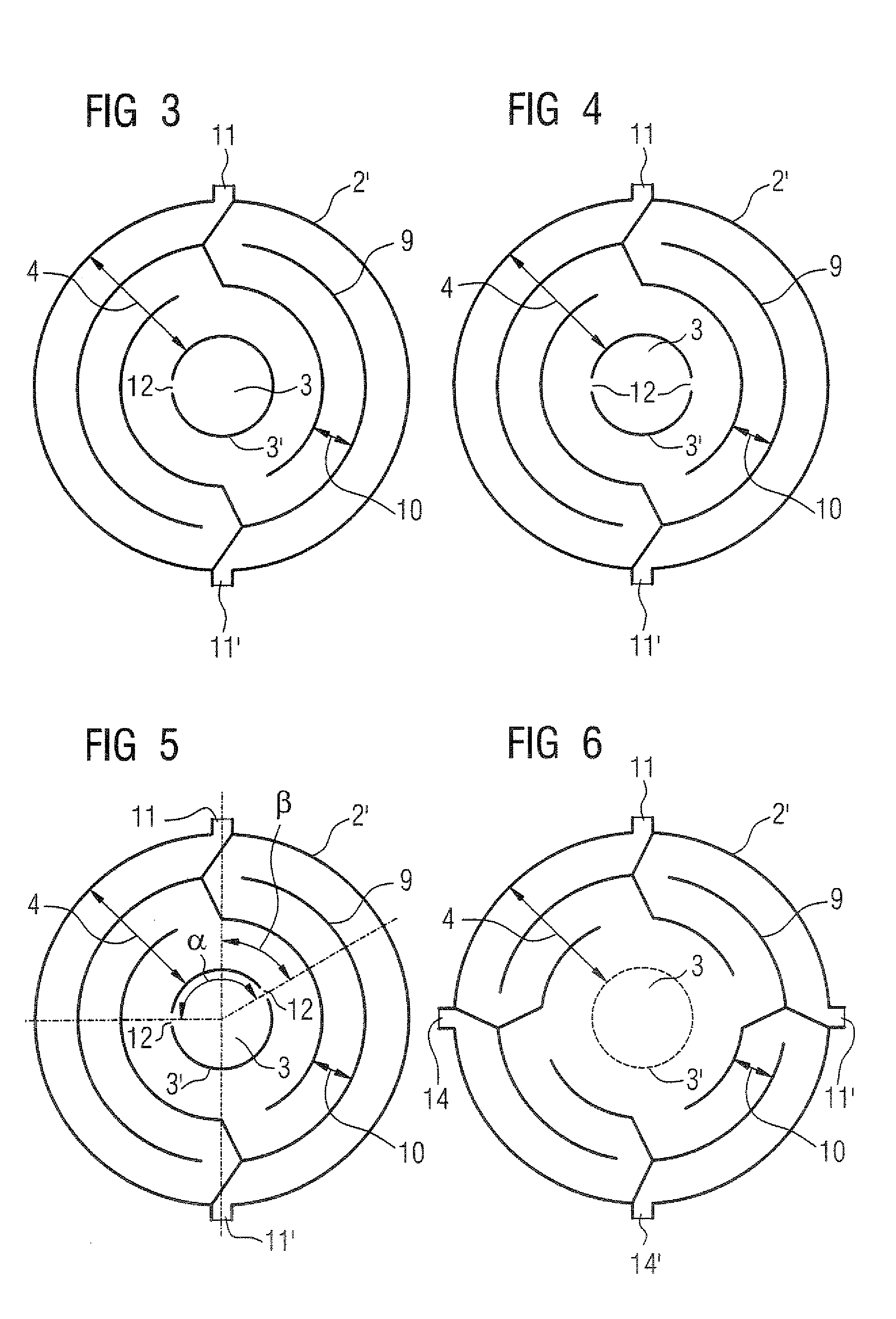
[0016]In an embodiment, the central region of the emitter plate is connected with the adjoining region only by a single connection web. Upon application of a heating current between the two heating current connections, no heating
voltage drop occurs in the central region of the emitter plate. The central region is therefore essentially heated only with heat conduction through the single connection web. Thus no electrons or almost no electrons, are emitted by the central region. This has the
advantage of allowing a design for the arrangement of the slits that was already created for an emitter plate emitting over its entire surface to essentially still be used. The arrangement of the slits in a region adjoining the central region is simply adopted; by contrast, for simplicity the central region is preferably free of slits over its entire surface, since it contributes nothing to the emission. Costs can thus be saved in the design of the emitter plate.
[0019]The emitter plate is advantageously connected to at least two circuits such that, in operation, a lower
current density exists in the central region than in the adjoining region. Since the lower
current density is achieved in the central region by a combination of the arrangement of the slits and the heating current connections, the central region can essentially be free of slits over the entire surface. A high
mechanical stability of the emitter plate thereby results. An
advantage that makes the increased effort of the connection to at least two circuits worthwhile is the fact that the
temperature gradient on the emitter plate, and thus the
electron density distribution of the electrons emitted by the emitter plate, can be provided in a continuously variable manner dependent on the arrangement of the slits and the arrangement of the current connections.
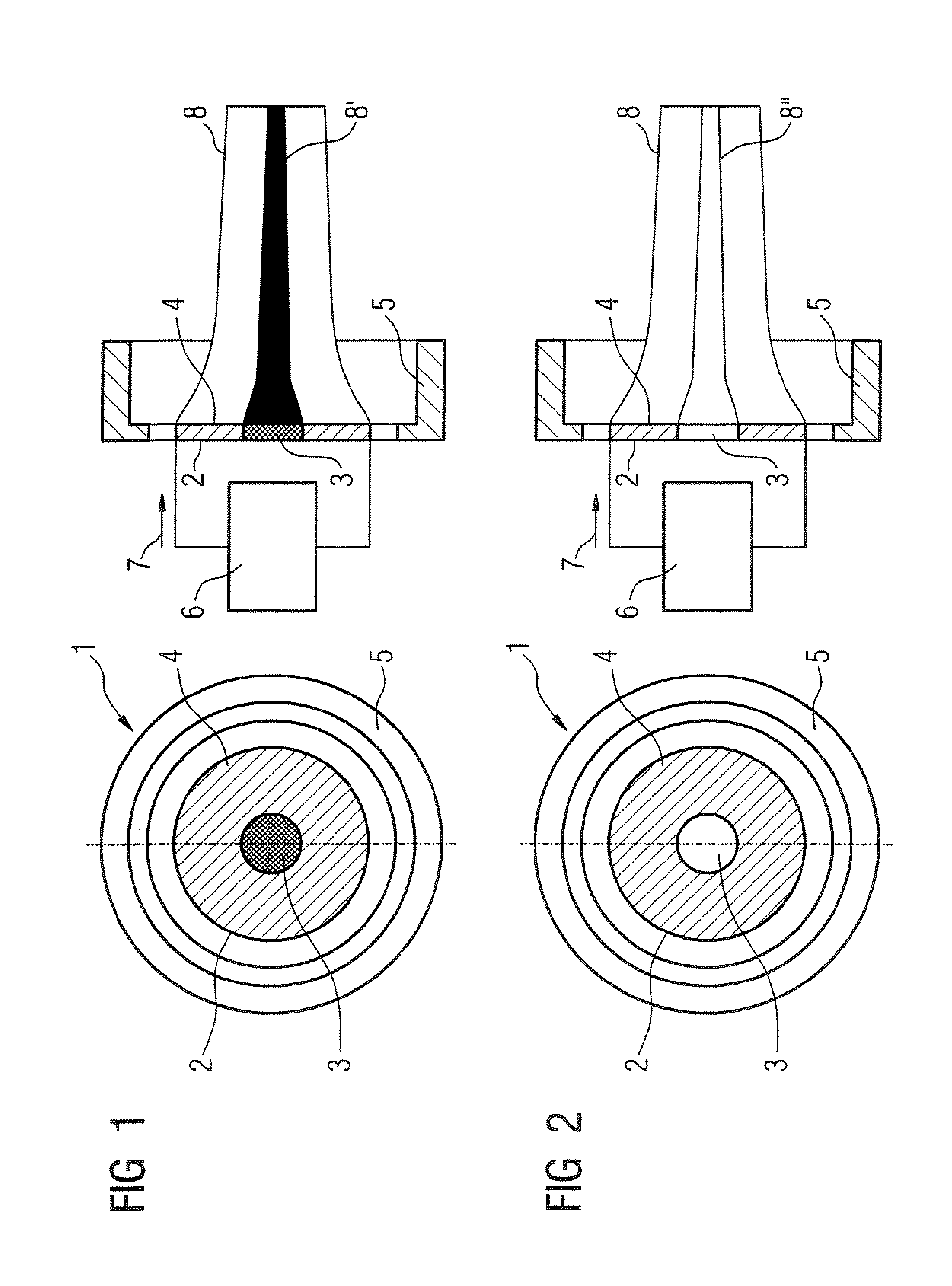
[0022]In a further embodiment, the emitter arrangement has, as the aforementioned structure, a diaphragm plate that is located before the central region. A conventional surface emitter can be used in this embodiment. The electrons emitted from the central region of this surface emitter are accelerated toward the diaphragm and strike on this diaphragm. They are therefore not accelerated toward the
anode. The
electron density distribution of a conventional emitter plate with a diaphragm arranged before the central region of this emitter plate therefore results in an
electron density distribution that is likewise less in the central region than in the adjoining region. No additional costs arise in the design of the surface emitter due to the use of a conventional surface emitter. The diaphragm plate additionally protects the surface emitter from damage due to ions accelerated from the anode toward the
cathode, such that the surface emitter must be changed significantly less often relative to an arrangement without diaphragm plate.

