This helps you quickly interpret patents by identifying the three key elements:
Problems solved by technology
Method used
Benefits of technology
Problems solved by technology
It is, however, difficult to form a thin film on a substrate because a liquid having viscosity is coated.
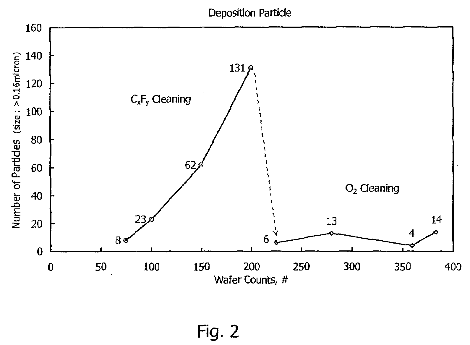
The unwanted film on the inner parts of the chamber produces particles which deposit on a substrate during CVD processing and deteriorate the quality of a film on the substrate.
Accumulation of unwanted adhesive products on surfaces of electrodes may affect plasma generation or distribution over a substrate and may cause damage to the electrodes.
Further, unwanted adhesive products may cause generation of contaminant particles.
However, the above conventional methods are not effective in cleaning a carbon-based film such as the amorphous carbon film including diamond-like carbon film and the carbon polymer film described above, which have high carbon contents.
Method used
Image
Click on the blue label to locate the original text in one second.
Reading with bidirectional positioning of images and text.
Examples
example 1
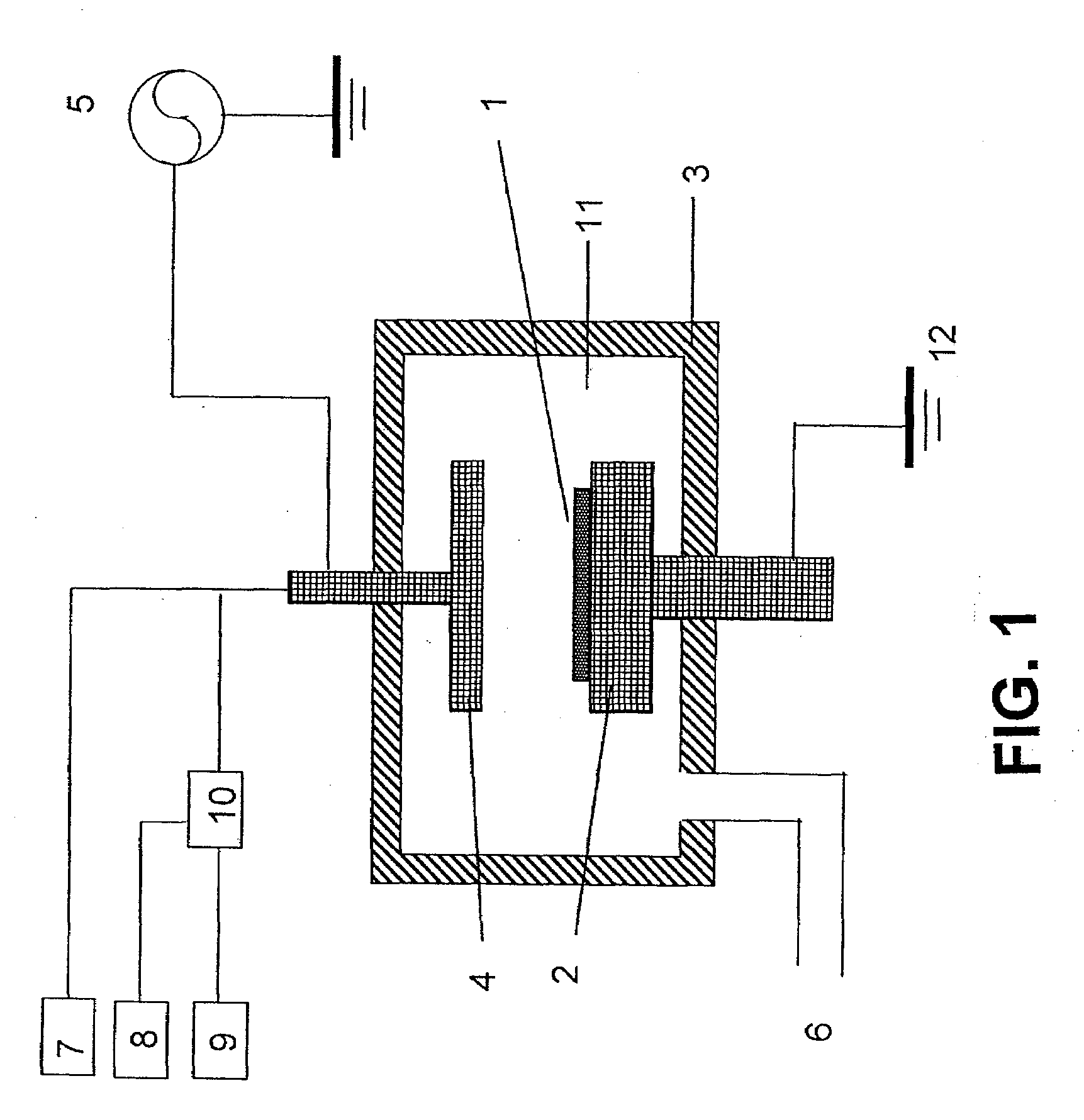
[0081]As a cleaning gas, O2 gas was solely used. Cleaning conditions in this example and cleaning results are shown as follows. A cleaning rate (etching rate) was evaluated at a center of the upper electrode (showerhead) and an inner wall facing a gate valve.
[0091]Under the same conditions as in Example 1 except for the pressure which was controlled at 533 Pa. A cleaning rate (etching rate) was evaluated at a center of the upper electrode (showerhead) and an inner wall facing a gate valve.
[0095]As shown above, by increasing the cleaning pressure from 150 Pa to 533 Pa, the cleaning rate at the electrode increased from 460 nm / min to 1150 nm / min which is 2.5-fold. On the other hand, the cleaning rate on the inner wall decreased from 320 nm / min to 50 nm / min which is less than 1 / 6-fold. By using O2 gas as the cleaning gas, the ratio of a cleaning rate at the electrode to a cleaning rate on the inner wall can highly be manipulated by changing the pressure. In the above examples, the ratio was changed from 2.5 to 1 / 6.
example 3
[0096]As a cleaning gas, N2O gas was solely used. Cleaning conditions in this example and cleaning results are shown as follows. A cleaning rate (etching rate) was evaluated at a center of the upper electrode (showerhead) and an inner wall facing a gate valve.
PUM
Property
Measurement
Unit
Temperature
aaaaa
aaaaa
Temperature
aaaaa
aaaaa
Fraction
aaaaa
aaaaa
Abstract
A method of self-cleaning a plasma reactor upon depositing a carbon-based film on a substrate a pre-selected number of times, includes: (i) exciting oxygen gas and / or nitrogenoxide gas to generate a plasma; and (ii) exposing to the plasma a carbon-based film accumulated on an upper electrode provided in the reactor and a carbon-based film accumulated on an inner wall of the reactor.
Description
CROSS-REFERENCE TO RELATED APPLICATIONS[0001]This application claims the benefit of U.S. Provisional Application No. 60 / 745,102, filed Apr. 19, 2006, the disclosure of which is herein incorporated by reference in its entirety.BACKGROUND OF THE INVENTION[0002]1. Field of the Invention[0003]The present invention relates to a method of self-cleaning of a carbon-based film deposited inside a reactor.[0004]2. Description of the Related Art[0005]In semiconductorprocessing techniques, optical films such as antireflective films and hard masks are used. In conventional techniques, these films are formed mainly by a technique called a coating method. The coating method forms highly functional polymer films by coating a liquid material and sintering it. It is, however, difficult to form a thin film on a substrate because a liquid having viscosity is coated. As semiconductorchip sizes continue to shrink, more thinned and higher-strength films are required.[0006]As an advantageous method for a...
Claims
Application Information
Patent Timeline
Application Date:The date an application was filed.
Publication Date:The date a patent or application was officially published.
First Publication Date:The earliest publication date of a patent with the same application number.
Issue Date:Publication date of the patent grant document.
PCT Entry Date:The Entry date of PCT National Phase.
Estimated Expiry Date:The statutory expiry date of a patent right according to the Patent Law, and it is the longest term of protection that the patent right can achieve without the termination of the patent right due to other reasons(Term extension factor has been taken into account ).
Invalid Date:Actual expiry date is based on effective date or publication date of legal transaction data of invalid patent.

