Optical scanning device, optical writing device, and image forming apparatus

a scanning device and optical writing technology, applied in the field of optical scanning devices, optical writing devices, image forming apparatuses, can solve the problems of increasing power consumption and noise, heat generation, and reducing the durability of optical components, and thereby increasing the diameter

Active Publication Date: 2007-11-01
RICOH KK
View PDF25 Cites 111 Cited by
  • Summary
  • Abstract
  • Description
  • Claims
  • Application Information

AI Technical Summary

Benefits of technology

[0023] It is an object of the present invention to at lea...

Problems solved by technology

The means, however, has some problems such as increase in power consumption and noise, heat generation, and degradation of its durability.
A spot diameter thereby increases, which causes image degradation.
In the conventional technology, however, necessary consideration is not given to the change in the focus position due to temperature of the optical system (scanning optical system) located downstream of the deflector.
In this method, however, an increase in the number of lenses results in an increase in cost.
Even in this case, a piece of glass lens is required, which also causes the increase in cost.
However, the scanning lens has a wide range through which a light flux passes, and requires time for machining the diffractive optical surface, which causes an increase in cost.
The conventional technologies, however, have a problem specific to the multibeam.
The problem is such that a wavelength difference between beams is not mentioned, and that even if performance of one beam can be acquired, performance of another beam cannot be acquired.
For high image ...

Method used


Image

  • Optical scanning device, optical writing device, and image forming apparatus
  • Optical scanning device, optical writing device, and image forming apparatus
  • Optical scanning device, optical writing device, and image forming apparatus

Examples


first embodiment

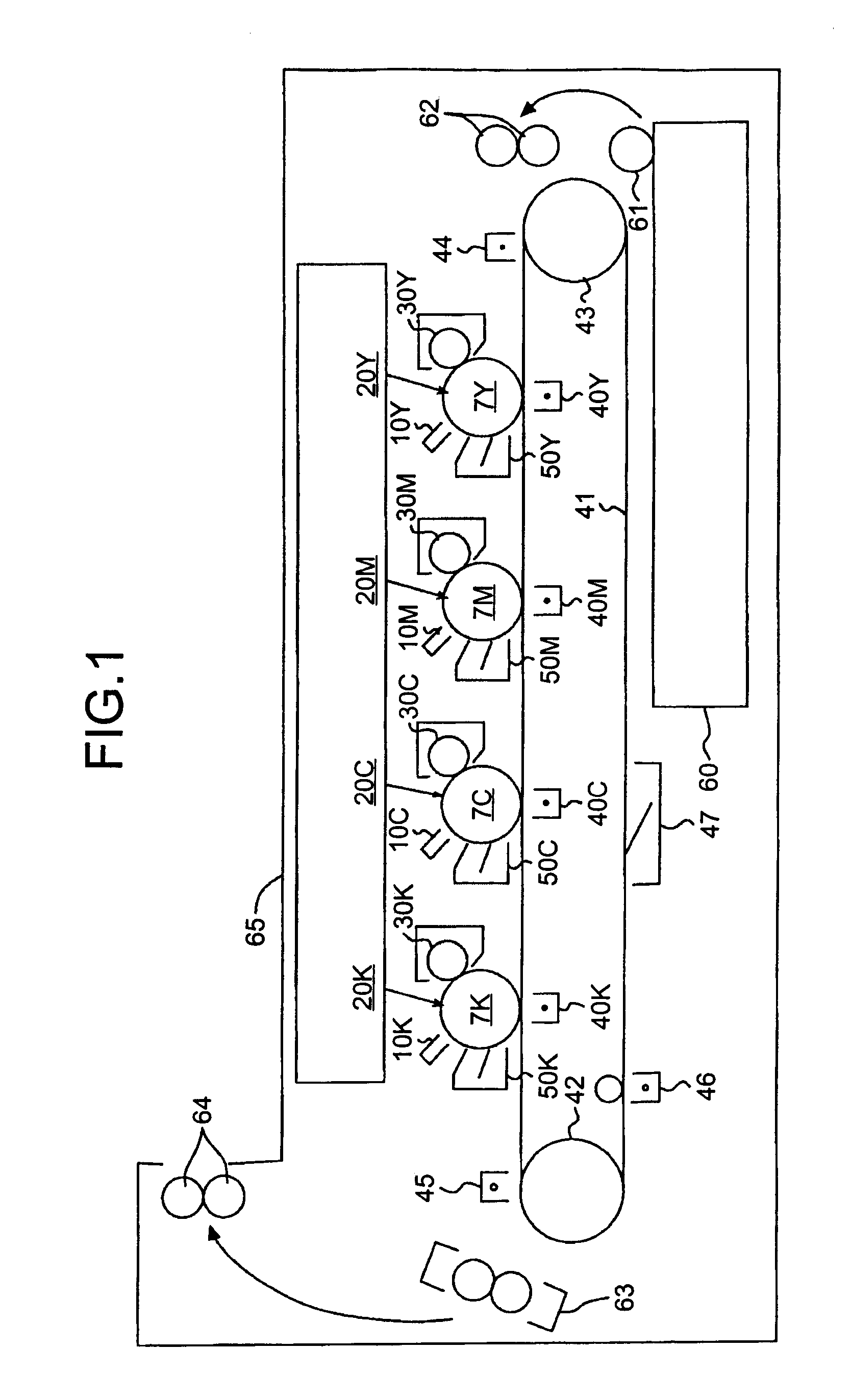
[0064] The optical scanning device explained later is used for the image forming apparatus having the configuration and operations, and it is thereby possible to obtain a stable beam-spot diameter at any time and implement a compact and low-cost image forming apparatus suitable for high-resolution printing.

[0065] The configuration, operation, and functional effect of the optical scanning device according to the first embodiment are explained in detail below.

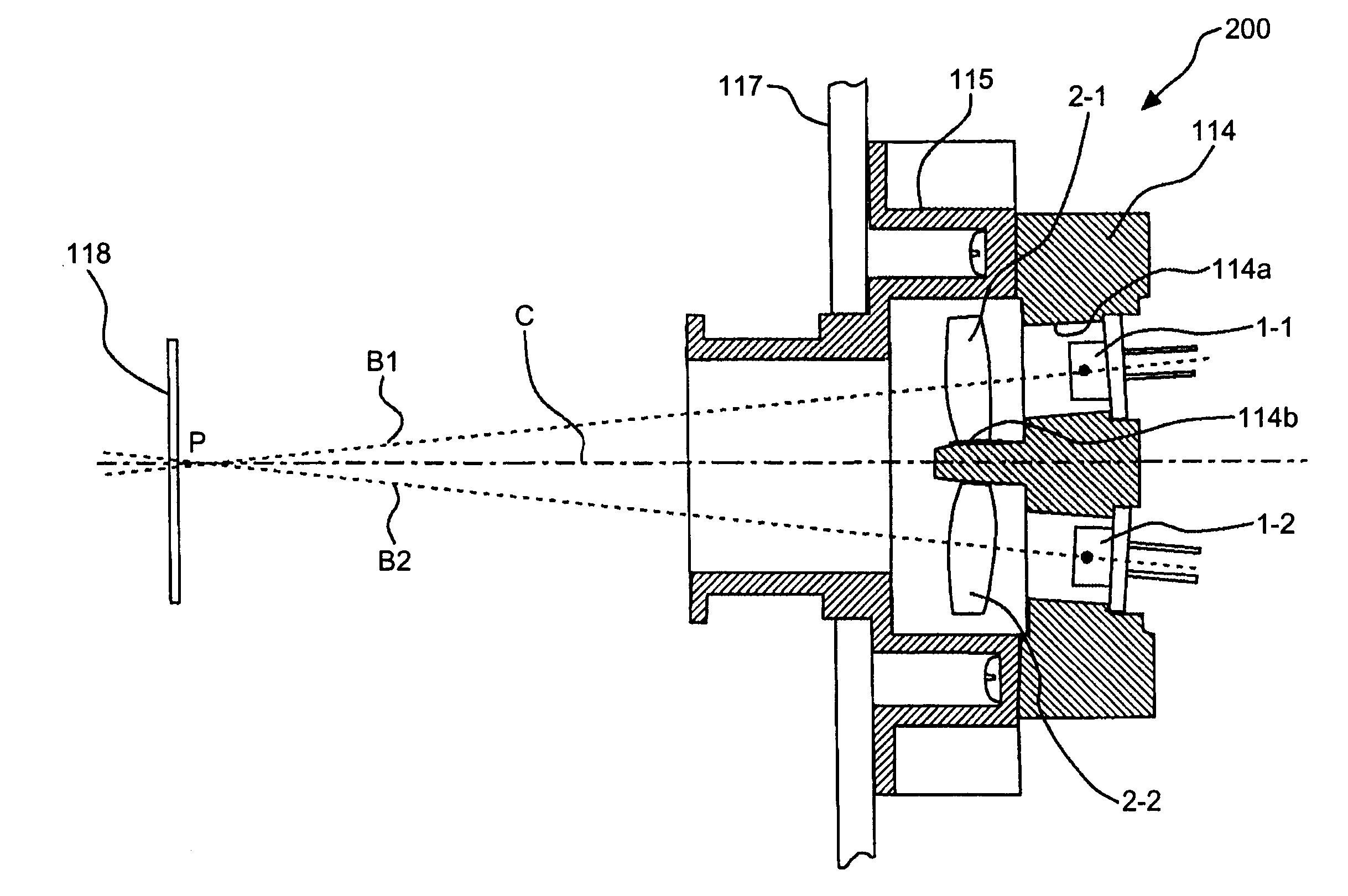
[0066] The optical scanning device according to the first embodiment includes a first optical system for guiding light beams emitted from a plurality of light emitting units to an optical deflector, and a second optical system for collecting the light beams deflected by the optical deflector onto the surface to be scanned to form a light spot and for optically scanning the surface to be scanned. The optical scanning device has characteristics as follows.

[0067] More specifically, at least one of the first optical system and the...

second embodiment

[0175] The configuration, operation, and functional effect of an optical scanning device are explained in detail below with reference to the accompanying drawings.

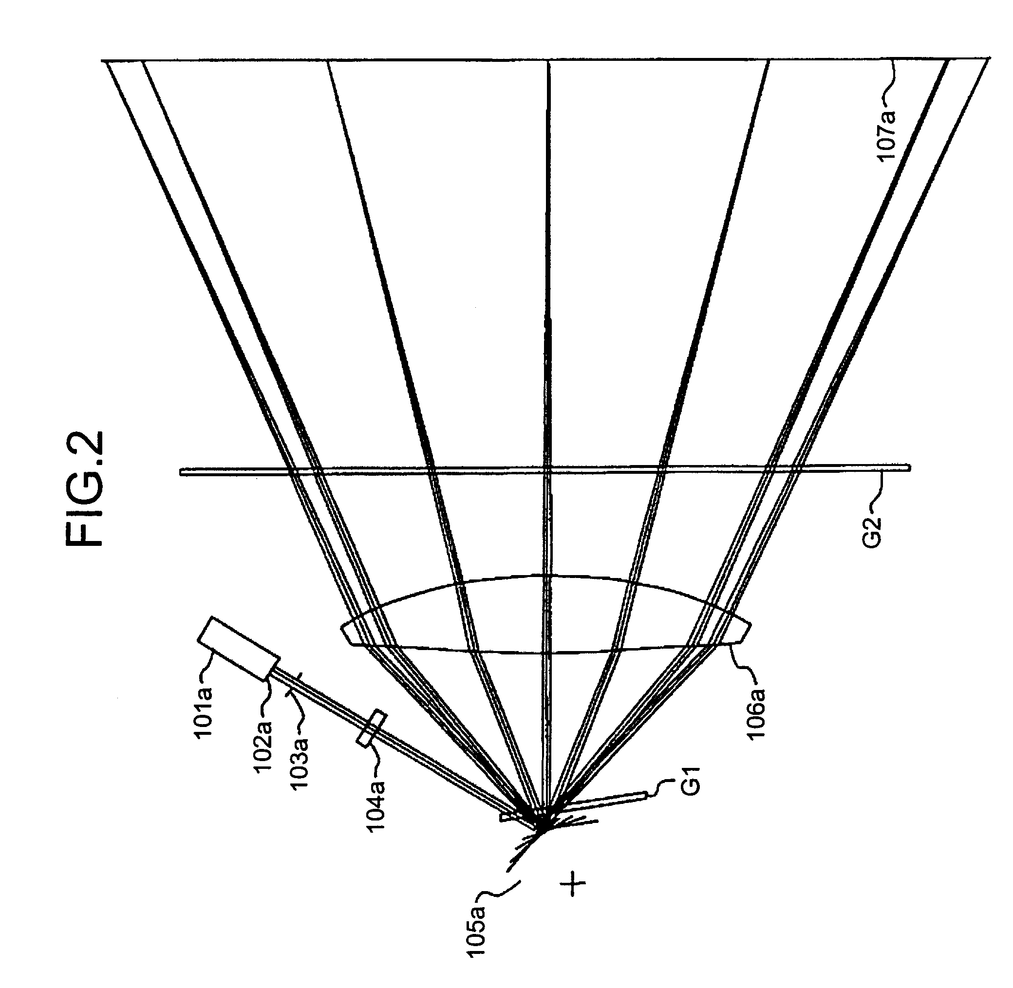
[0176]FIG. 11 is an example of a basic configuration of the optical scanning device according to the second embodiment. In FIG. 11, an optical system forming the optical scanning device is developed on a plane (called “main-scanning plane” or “main-scanning cross section”) passing through the optical axis and parallel to the main scanning direction (a deflecting / scanning direction by a deflecting unit).

[0177] As shown in FIG. 11, the optical system includes light source units (semiconductor lasers) 101b and 101c, coupling lenses (first lenses) 102b and 102c, an aperture (aperture stop) 103b, an anamorphic lens (second lens) 104b, a polygon mirror 105b of a deflector (polygon scanner) which is a deflecting unit (only one deflection facet of the polygon mirror is shown in FIG. 11), a scanning lens 106b, an image-plane-side...

third embodiment

[0239] Although the scanning optical system in FIG. 15 is formed with only one scanning lens 106c, even if a plurality of scanning lenses are used, the same effect of the third embodiment is obtained. A deflected light flux is reflected by a synchronization mirror 122 before optical scanning each time the deflected light fluxes optically scan the photosensitive element 7, and the reflected light is collected to a synchronization detector 124 in the main scanning direction by a synchronization lens 123. The synchronization detector 124 receives the reflected light to output a detection signal, and a write-start timing for optical scanning is determined based on the output signal.

[0240] The “spot diameter of a light spot” in this specification is defined as 1 / e2 intensity in a line spread function of a light intensity distribution in the light spot on the surface to be scanned. The “line spread function” is defined as follows. When a light intensity distribution of a light spot f(Y, Z...


PUM


Abstract

An optical scanning device includes a first optical system for guiding light beams emitted from a plurality of light emitting units to an optical deflector, and a second optical system for focusing the light beams to optically scan a surface to be scanned. At least one of the first optical system and the second optical system includes a resin lens having a diffractive surface. The diffractive surface includes a diffractive portion and a refractive portion. A power of the diffractive portion and a power of the refractive portion cancel each other.

Description

CROSS-REFERENCE TO RELATED APPLICATIONS [0001] The present document incorporates by reference the entire contents of Japanese priority documents, 2006-123329 filed in Japan on Apr. 27, 2006, 2006-125792 filed in Japan on Apr. 28, 2006, and 2006-206680 filed in Japan on Jul. 28, 2006. BACKGROUND OF THE INVENTION [0002] 1. Field of the Invention [0003] The present invention relates to an optical scanning device, an optical writing device, and an image forming apparatus. [0004] 2. Description of the Related Art [0005] An image forming apparatus such as a digital copier and a laser printer forms a latent image by radiating a light beam to a photosensitive element, which is an image carrier, using an optical scanning device. Recently, high-density image formation through optical scanning is developing, and a smaller beam-spot diameter on the photosensitive element is demanded of the image forming apparatus. [0006] In addition to the high density, high-speed image formation is progressing...

Claims


Application Information

Patent Timeline
IPC IPC(8): G02B26/08
CPCG02B26/124G02B27/4283G02B27/4227G02B27/42
Inventor SAKAI, KOHJIHAYASHI, YOSHINORIUEDA, TAKESHIICHII, DAISUKESAISHO, KENICHIROH
Owner RICOH KK
Why Eureka
Try Eureka