Method and apparatus for multi-phase power conversion

a multi-phase power conversion and power factor technology, applied in the field of multi-phase power conversion, can solve the problems of increasing the cost of power converters, complexity and size, and the difficulty of acquiring and maintaining phase locks, and achieves the effects of reducing or eliminating the impact of inductor tolerance, improving circuit efficiency, and improving power factor

Active Publication Date: 2007-11-01
TEXAS INSTR INC
View PDF14 Cites 66 Cited by
  • Summary
  • Abstract
  • Description
  • Claims
  • Application Information

AI Technical Summary

Benefits of technology

[0030]The disclosed system and method contribute to improving circuit efficiency by improving power factor while maintaining zero volt and zero current switching. The disclosed system and method also operate to reduce or eliminate the impact of inductor tolerances upon phase separation mismatches. That is, because the control operates based on zero current crossings, variations in the tolerances of the inductors do not impact the control of phase separation.

Problems solved by technology

Due to the variable frequency nature of the power supply switching, it can be challenging to synchronize the various phases to obtain one or more of the above-described advantages, especially as frequency changes to deliver desired output power characteristics.
This arrangement calls for special purpose components that can add to power converter cost, complexity and size.
One drawback to this approach is the challenge of acquiring and maintaining a phase lock over a wide range of conditions.
The PLL capture range must encompass the difference between the free-running frequencies of the master and slave(s), which may prove difficult or costly in practice.
For example, if a change in load demand causes switching frequency to change rapidly, a large momentary frequency error may result, which can cause loss of phase lock.

Method used


Image

  • Method and apparatus for multi-phase power conversion
  • Method and apparatus for multi-phase power conversion
  • Method and apparatus for multi-phase power conversion

Examples


Embodiment Construction

[0062]This application claims the benefit of U.S. Provisional Application No. 60 / 796,420, filed May 1, 2006, the entire content of which is hereby incorporated herein by reference.

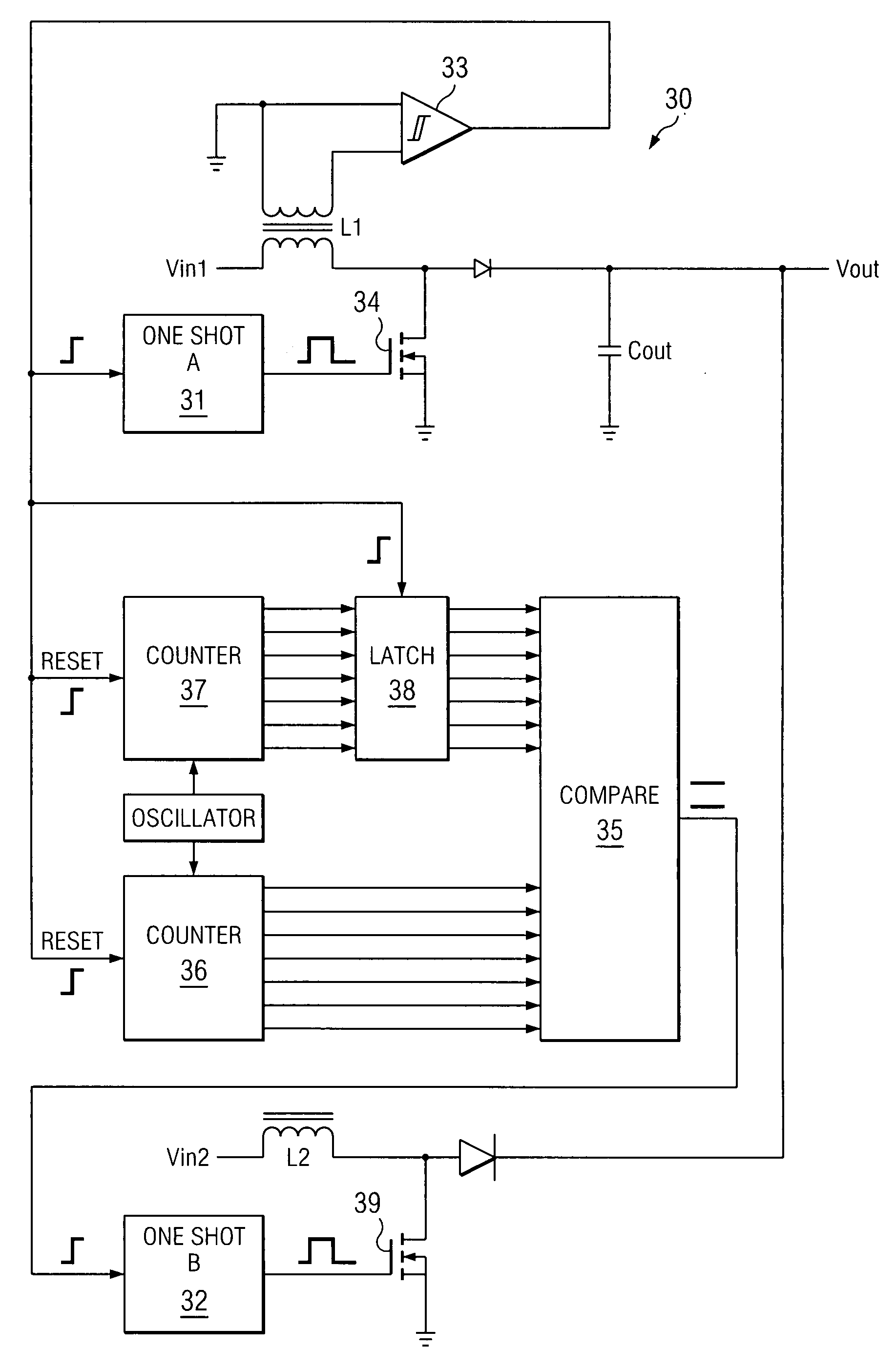
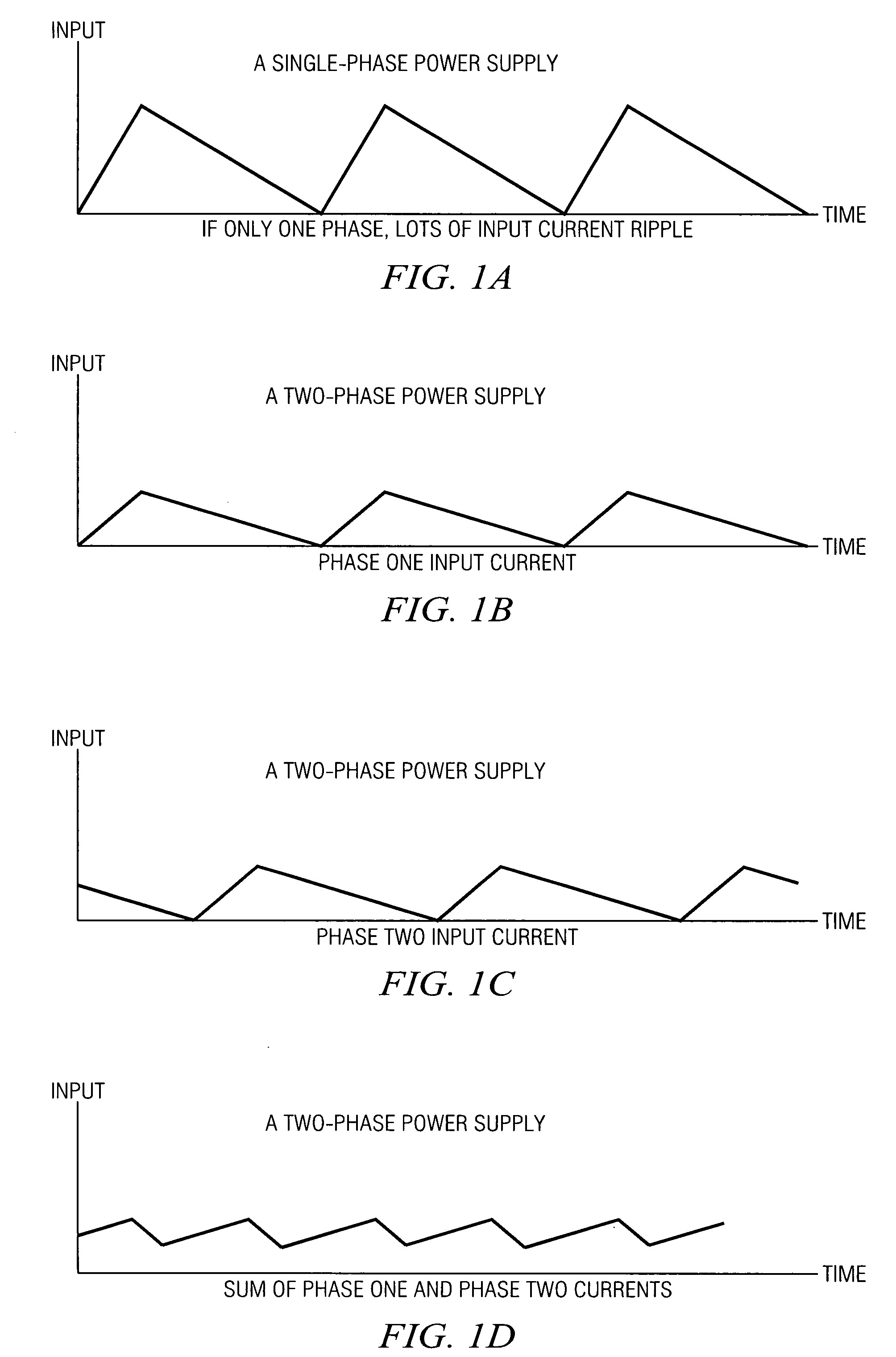
[0063]Referring to FIGS. 1a-1d, plots of input current verses time are illustrated for a single phase power supply and a power supply with two interleaved phases. FIG. 1a illustrates a single phase power supply that exhibits a significant amount of input current ripple. FIGS. 1b-1d illustrate input current for each of two phases, and the sum of the current of the two phases, respectively. The sum of the two current phases shown in FIG. 1d produces a current with lower peak current, lower ripple, and a ripple frequency that is twice the frequency of the two input current phases. A variable frequency PWM control may be used to produce an interleaved multiphase power supply with such an advantageous summed current. However, the realization of the variable frequency PWM control is somewhat challenging in that ...


PUM


Abstract

A system and method for power conversion synchronizes multiple phases at a desired phase angle difference. The power conversion involves variable frequency switching, fixed on-time and provides power factor correction. A relative measure of a phase angle difference between two phases permits each phase to be controlled to obtain the desired phase angle difference. The power conversion involves transition mode switching to help reduce switching losses. A phase angle difference detector may be provided for each phase. The various phases may have different inherent frequencies that vary with switching frequency, and are synchronized to an average frequency. Current measures can be taken with a single component, such as a resistor. A maximum frequency control limits period width to avoid high frequency switching. An added switch on time improves input voltage crossover distortion. One or more phases can be deactivated in light load conditions.

Description

CROSS REFERENCE TO RELATED APPLICATIONS[0001]This application is based on and claims benefit of U.S. Provisional Application No. 60 / 796,420, filed May 1, 2006. This application is related to U.S. application Ser. No. 11 / 708,820 (TI-62124) filed Feb. 21, 2007, U.S. application Ser. No. 11 / 799,181 (TI-63508) filed May 1, 2007, and U.S. application Ser. No. 11 / 799,190 (TI-63804) filed May 1, 2007.STATEMENT REGARDING FEDERALLY SPONSORED RESEARCH OR DEVELOPMENT[0002]Not ApplicableBACKGROUND OF THE INVENTION[0003]1. Field of the Invention[0004]The present invention relates generally to multiple power converters used in conjunction, and relates more particularly to synchronization of power converters used in conjunction with interleaved phases.[0005]2. Description of Related Art[0006]Performance improvements in interleaved, multiphase power supplies result from advantages such as reduced input current ripple, reduced peak output current and higher frequency output ripple current. The highe...

Claims


Application Information

Patent Timeline
Patent Type & Authority Applications(United States)
IPC IPC(8): H02M7/515
CPCH02M1/4216Y02B70/126H02M1/4225Y02B70/10
Inventor NEIDORFF, ROBERT ALANCOHEN, ISAACVALLEY, RICHARD L.
Owner TEXAS INSTR INC
Why Eureka
Try Eureka