System and method for in vivo imager with stabilizer

a stabilizer and imager technology, applied in the field of system and method of in vivo stabilizer, can solve the problems of reduced resolution and numerical aperture at large field angles, increased distortion of simple wide-angle lenses, and ineffective types of configuration

Inactive Publication Date: 2007-11-01
CAPSO VISION INC
View PDF34 Cites 55 Cited by
  • Summary
  • Abstract
  • Description
  • Claims
  • Application Information

AI Technical Summary

Problems solved by technology

Unfortunately, a simple wide-angle lens will exhibit increased distortion and reduced resolution and numerical aperture at large field angles.
A capsule camera is constrained to be compact and low-cost, and these types of configurations are not cost effective.
Further, these conventional devices waste illumination at the frontal area of these lenses, and thus the power used to provide such illumination is also wasted.
Since power consumption is always a concern, such wasted illumination is a problem.
Still further, since the intestinal wall within the filed of view extends away from the capsule, it is both foreshortened and also requires considerable depth of field to image clearly in its entirety.
Depth of field comes at the expense of exposure sensitivity.
Also, whether in a large or small cavity, it is well known that there are sacculations that are difficult to see from a capsule that only sees in a forward looking orientation.
These ridges extend somewhat perpendicular to the walls of the organ and are difficult to see behind.
Conventional devices are not able to see such surfaces, since their FOV is substantially forward looking.
Since conventional capsules are unable to see the hidden areas around the ridges, irregularities may be missed, and critical diagnoses of serious medical conditions may be flawed.
Also, if the LED (light emitting diode) illuminators provide uniform flux across the angular FOV, then point A will be more brightly illuminated than point B and point B more than point C. Thus, an optimal exposure for point B results in over exposure at point A and under exposure at point C. For each image, only a relatively small percentage of the FOV will have proper focus and exposure, making the system inefficient.
This does not completely obviate the problem of wasteful illumination, and furthermore creates other power demands when rotating.
Also, t

Method used


Image

  • System and method for in vivo imager with stabilizer
  • System and method for in vivo imager with stabilizer
  • System and method for in vivo imager with stabilizer

Examples


Embodiment Construction

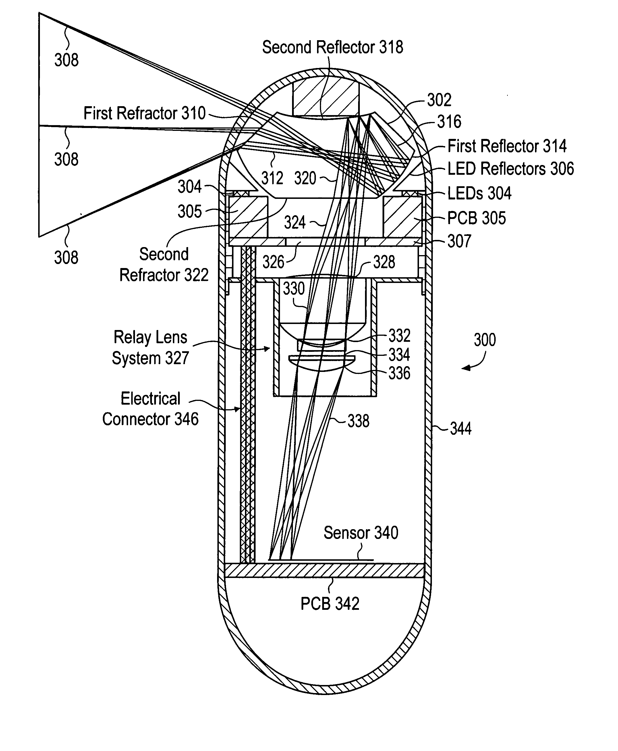
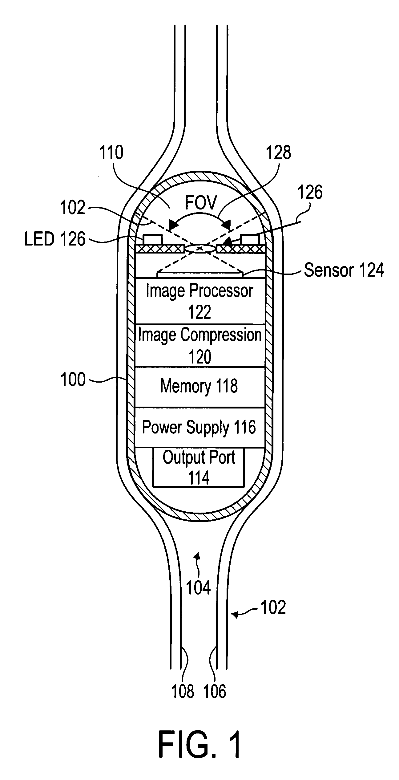
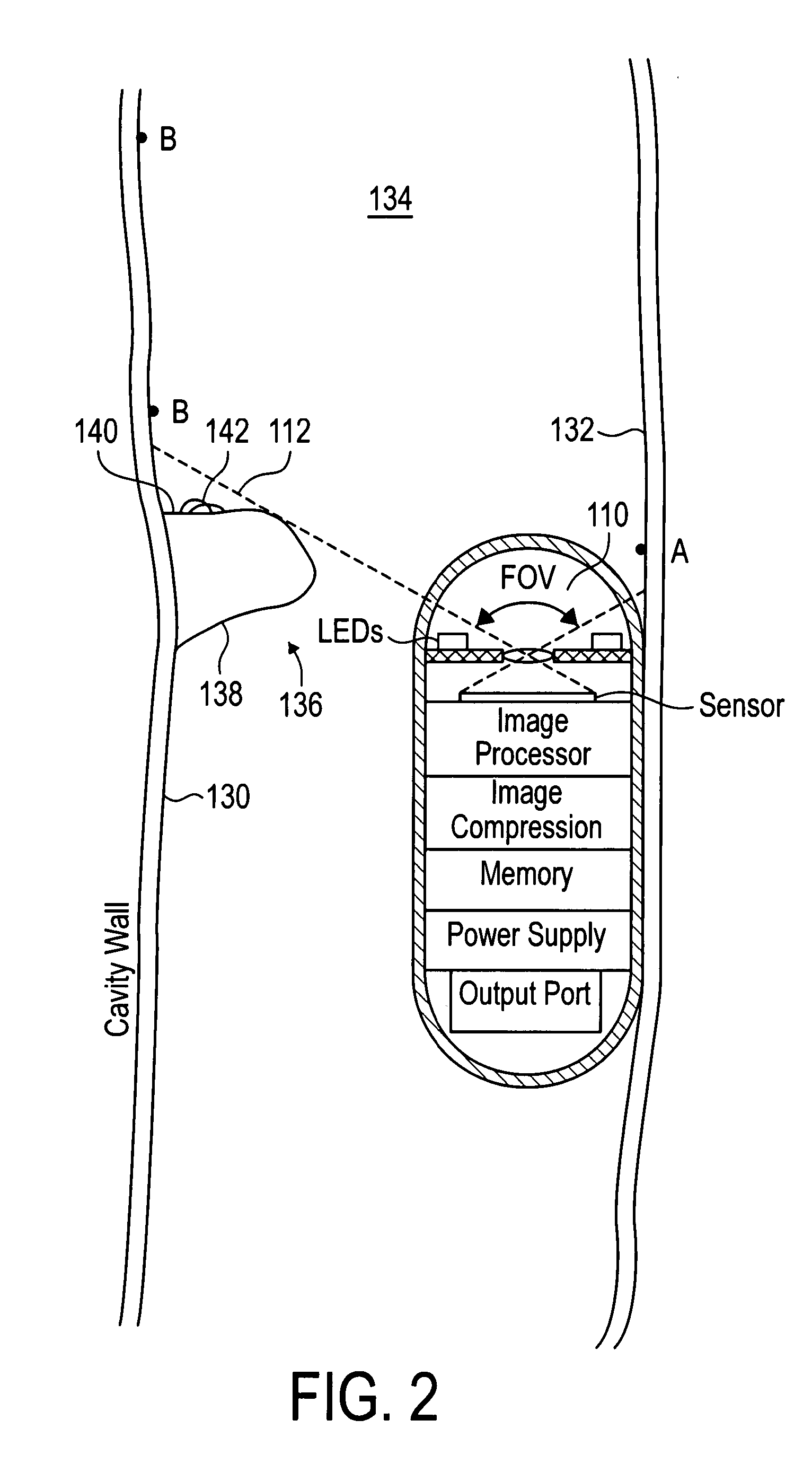
[0024] Generally, the invention is directed to an in vivo camera system, where the system includes a capsule having at least one balloon configured to orient the capsule in a consistent orientation relative to an internal organ, and an imager encased within the capsule having a field of view that includes substantially all directions perpendicular to a subject tissue surface for capturing a peripheral image of tissue surface surrounding the capsule on a single image plane. The at least one balloon may also help to dilate an organ that might other wise be collapsed and folded so that the interior surface is more fully exposed and visible. The imager may include a panoramic camera encased within the capsule and configured to capture an image of tissue surface about the capsule on a single image plane. The orientation stabilizer may be configured to expand from at least two points on the capsule to stabilize the orientation of the capsule while traveling through an organ such as the co...


PUM


Abstract

A swallowable capsule with a camera and a memory for imaging the colon. Standard semiconductor memory (memories made of standard memories processes or processes modified from standard process by adopting comprehensible silicon planar technology process steps) is used. This is made possible by the use of an optimal type of image compression that can be performed with limited processing power and limited memory (e.g., without requiring a full size frame buffer). Also, controls on the number of images taken are used in one embodiment.

Description

BACKGROUND OF THE INVENTION [0001] Various autonomous devices have been developed that are configured to capture an image from within in vivo passages and cavities within a body, such as those passages and cavities within the gastrointestinal (GI) tract. These devices typically comprise a digital camera housed within a capsule along with light sources for illumination. The capsule may be powered by batteries or by inductive power transfer from outside the body. The capsule may also contain memory for storing captured images and / or a radio transmitter for transmitting data to an ex vivo receiver outside the body. [0002] A common diagnostic procedure involves the patient swallowing the capsule, whereupon the camera begins capturing images and continues to do so at intervals as the capsule moves passively through the cavities made up of the inside tissue walls of the GI tract under the action of peristalsis. The capsule's value as a diagnostic tool depends on it capturing images of the...

Claims


Application Information

Patent Timeline
IPC IPC(8): A61B1/00
CPCA61B1/041A61B1/06A61B1/0684A61B1/0615A61B1/00177
Inventor WANG, KANG-HUAIWILSON, GORDON
Owner CAPSO VISION INC
Why Eureka
Try Eureka