[0029]An object of the present invention, therefore, is to provide a method for controlling an agricultural machine system of the type described initially and to create an
automatic control system for carrying out this method, with which the disadvantages described above are prevented.
[0034]The various functions typically last for an exactly defined period of time. In order to carry out a certain function, it must therefore be ensured that the hydraulic valve is actuated for a certain length of time when a certain attachment is attached. A time-dependent control of this type can also be updated dynamically, and it can be dependent on which working steps have been carried out previously or afterward. The
oil pressure in the hydraulic lines is higher, e.g., if the engine speed was increased before the particular working step. An attachment can then be hydraulically displaced more quickly, and the period of time for actuating the hydraulic valve can therefore be shorter than it is when the engine speed is not increased until after the particular time-controlled working step, for instance.
[0036]If, in reality, the headland track is shorter than planned and there is therefore not as much time available as required for the originally planned sequence of headland working steps, the sequence can be updated as follows: First, the header is lowered, then the engine speed is reduced when the machine system exits the old working track, and, vice versa, when the machine system enters the new working track, the engine speed is increased, then the header is lowered. The
advantage of this is that, due to the higher engine speed, the
oil pressure is higher when the height of the header is adjusted, thereby enabling the header to be adjusted more quickly. If there is only a very short amount of time available for turning, the sequence of headland working steps can also be updated such that the engine speed is not reduced at all, and the only tasks carried out are that the header is lifted and then lowered.
[0046]The control method therefore ultimately functions independently of which working tracks are entered in succession. As such, it is always possible—as it is with most classical working strategies—to select the closest adjacent driving track. It is also possible to enter any other optimal driving track that was selected within the framework of
route planning. In particular, it is also possible at any time for the driver to specify which driving track he wants to enter next, e.g., a driving track with special properties or a driving track on which stored
crop material can be unloaded, or a driving track with a certain
crop quality. The driver can also select a certain driving track with a path marking that was put in place in advance. Via the dynamic updating of the headland track, the driver can select a different driving track—while driving along a track ahead of it or while driving along the planned headland track—thereby enabling him to react flexibly to any event and subsequently continue driving down a newly calculated, optimized route.
[0047]Particularly preferably, when the route for the machine system is created, the selection and
layout of the working tracks and the sequence in which the working tracks will be driven along are carried out depending on certain parameters of the machine system, particularly its working width and / or
turning radius. Particularly preferably, the working tracks are selected and laid out, and their sequence is selected depending on the course of possible headland tracks between the working tracks. By linking the optimization of the working tracks for working the territory with possible headland tracks in this manner it can be ensured that the working tracks per se as well as the time and distances required to travel along the headland tracks are taken into account in the
route planning. Due to this
intelligent planning of the turning maneuver, efficiency can be increased considerably. As described above, during travel along a working track, the sequence in which subsequent working tracks will be driven along is updated dynamically. For example, when it becomes clear that the grain tank of a
combine harvester is full and must be unloaded, the sequence of working tracks to be driven along must be reordered such that it is possible to unload the grain tank on the next working track.
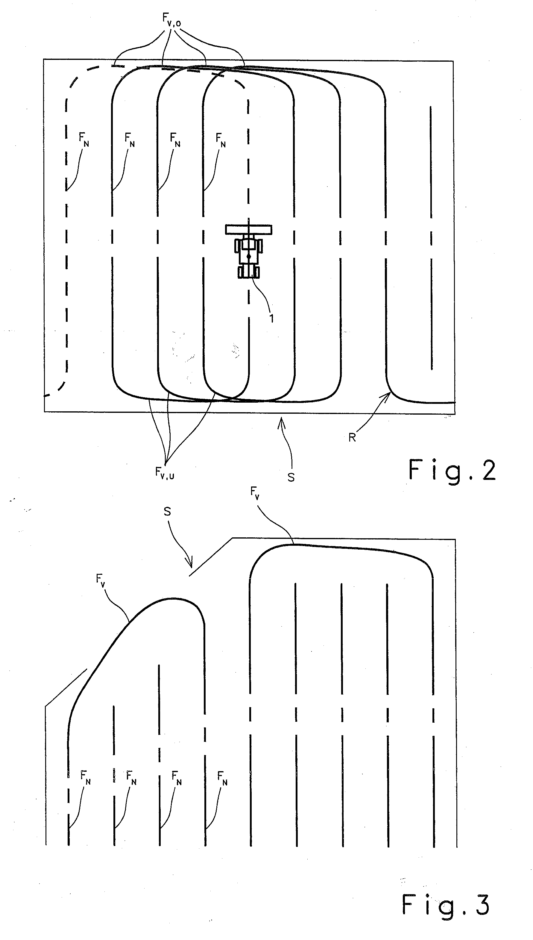
[0048]A headland track between two driving tracks can be generated preferably relatively easily using individual turning curves, each of which is defined by the following parameters:

