Heat recovery gas turbine in combined brayton cycle power generation

a gas turbine and combined cycle technology, applied in the direction of engines, machines/engines, mechanical equipment, etc., can solve the problems of nox removal technology and inability to achieve the required low emissions,

Inactive Publication Date: 2007-11-08
SIEMENS ENERGY INC
View PDF25 Cites 29 Cited by
  • Summary
  • Abstract
  • Description
  • Claims
  • Application Information

AI Technical Summary

Problems solved by technology

Since gas turbines themselves do not achieve the required low emissions, NOx removal technology must be applied to the combustion exhaust gas.

Method used


Image

  • Heat recovery gas turbine in combined brayton cycle power generation
  • Heat recovery gas turbine in combined brayton cycle power generation
  • Heat recovery gas turbine in combined brayton cycle power generation

Examples


Embodiment Construction

[0008] Gas turbine engines operate on a thermodynamic Brayton cycle, in which ambient air is drawn into a compressor and pressurized. The compressed air is heated in a generally constant-pressure process in a heating chamber that is open to both inflow and outflow. This is normally done by burning fuel in the compressed air in a combustion chamber, producing a hot working gas comprising combustion gasses. The heated air is then expanded through a turbine to extract energy in the form of shaft power. FIG. 3 illustrates aspects of an illustrative Brayton cycle comprising a series of transitions 1, 2, 3, and 4 of a working gas, starting from atmospheric pressure 10, then to compression 11, combustion 12, expansion through a turbine section 13, and exhaust 14.

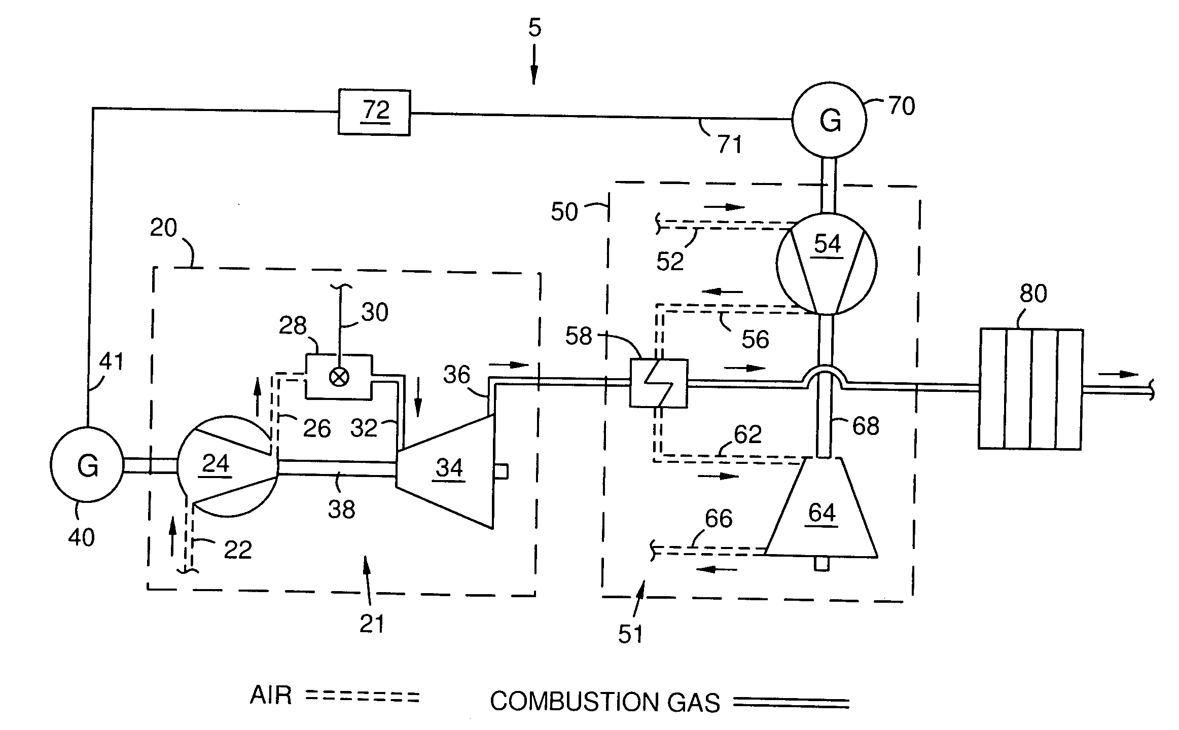
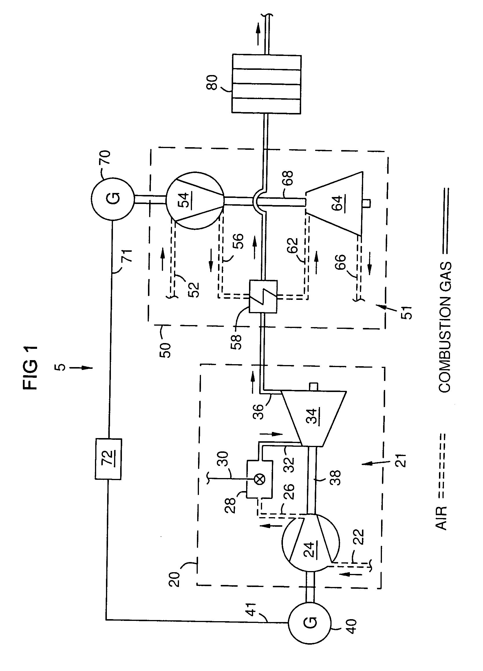
[0009] In accordance with an aspect of the invention FIG. 1 schematically shows a combined cycle power generator 5 comprising two cooperating Brayton cycles 20 and 50. The first Brayton cycle 20 may comprise a combustion turbine e...


PUM


Abstract

A combined Brayton cycle power plant (5). A combustion gas turbine engine (21) in the power plant uses a first Brayton cycle (20), and produces waste heat in an exhaust combustion gas (36). A heat exchanger (58) transfers the waste heat to a compressed working airflow (56) for a second Brayton cycle (50) in a heat recovery gas turbine engine (51). The heat transfer lowers the temperature of the combustion exhaust gas (36) to within an operating range of a conventional selective catalytic reduction unit (80), for efficient reduction of nitrogen oxide emissions to meet environmental regulations.

Description

FIELD OF THE INVENTION [0001] This invention relates to electric power generation, especially to combined cycle power generation using a gas turbine engine in a first power cycle that produces waste exhaust heat, and a waste heat recovery system driving a second power cycle. BACKGROUND OF THE INVENTION [0002] Electric power plants commonly use F-class gas turbine technology, which is distinguished by firing temperatures of about 1,300° C. and exhaust temperatures of over 580° C. A strong demand exists for turbine power plants with nitrogen oxide (NOx) emissions low enough to meet increasingly strict environmental regulations. Since gas turbines themselves do not achieve the required low emissions, NOx removal technology must be applied to the combustion exhaust gas. There are currently two main commercial alternatives for this: 1) Hot selective catalytic reduction (SCR), which can operate at the gas turbine exhaust temperature; and 2) Conventional SCR, which must operate at temperat...

Claims


Application Information

Patent Timeline
Patent Type & Authority Applications(United States)
IPC IPC(8): F02C9/00
CPCF02C6/18F05D2270/082F05D2220/76F05D2230/52Y02E20/16Y02A50/20
Inventor BRIESCH, MICHAEL S.WEBER, INGOMOULAVI, ABOL H.
Owner SIEMENS ENERGY INC
Why Eureka
Try Eureka