Method of Making a Magnetic Core Part

a magnetic core and resin molding technology, applied in the field of resin molding magnetic core parts, can solve the problems of cracks, inferior moldability or compactability of the most commonly used material, and material characteristics that are now at a limit in terms of material characteristics, so as to reduce the size of the magnetic core part, and increase the magnetic flux density

Active Publication Date: 2007-11-08
NTN CORP
View PDF5 Cites 25 Cited by
  • Summary
  • Abstract
  • Description
  • Claims
  • Application Information

AI Technical Summary

Benefits of technology

[0027] The present invention of the construction referred to above offers the following effects.
[0028] According to the present invention, because the soft magnetic green compact is insert molded into the resin composition, the magnetic flux density can be increased, compared with ordinary injection molded products, by positioning the soft magnetic green compact at a portion where an increase in magnetic flux density is desired, making it possible to reduce the size of the magnetic core part. Also, because the shape of the compact can be simplified, not only can the filling density be increased, but cracks that have been hitherto caused, for example, during bending of the electrode terminals can be also prevented. Further, if the hard magnetic green compact is positioned at a portion of a magnetic path, it provides the magnetic core part with a magnetic bias and, hence, the magnetic core part is hardly saturated even in a high magnetic field.
[0029] In addition, because the soft magnetic green compact or the hard magnetic green compact contains a binder having a melting point lower than the injection molding temperature, melting or softening of the binder in the soft or hard magnetic green compact occurs during the injection molding and, at the same time, an injection pressure is applied thereto, resulting in a status similar to the warm pressurization. Accordingly, compression progresses to improve the magnetic properties of the soft or hard magnetic green compact.
[0030] In the case where the hart magnetic green compact contains a thermosetting resin having a setting temperature lower than the injection molding temperature, hardening of the thermosetting resin commences during the injection molding. As a result, the density of the hard magnetic green compact increases to thereby avoid the generation of cracks that has been hitherto caused concurrently with improvement in magnetic properties or increase in strength.
[0031] If the soft or hard magnetic green compact is at least partly crushed during the injection molding, voids existing therein are released in the course of collapse of the soft or hard magnetic green compact, thereby improving the filling density of the entire compact and homogenizing it as compared with the case wherein the shape of the soft or hard magnetic green compact is left unchanged. If the collapse of the soft or hard magnetic green compact is caused locally, for example, at an end surface of the magnetic core part, an abrupt change in magnetic properties due to the presence or absence of the soft or hard magnetic green compact can be relieved.
[0032] Moreover, because the soft or hard magnetic green compact is insert molded together with a coil, the manufacturing process of the magnetic core part can be simplified. Also, the magnetic flux density can be partially increased or a magnetic bias can be effectively given by appropriately selecting the positional relationship between the coil and the soft magnetic green compact or the hard magnetic green compact and, accordingly, the size such as the coil diameter, the number of turns, or the height of the entire magnetic core part including the coil can be reduced as occasion demands. Further, because the resin composition protects the soft magnetic green compact or the hard magnetic green compact, there is no fear of cracks occurring that may be caused during the bending of the electrode terminals in association solely with the soft or hard magnetic green compact.

Problems solved by technology

However, ferrite material that is most frequently used now reaches a limit in terms of material characteristics, and a new material is being sought.
Although amorphous powder material superior in magnetic properties appears, it is inferior in moldability or compactability to the conventional material, and the practical use thereof is accordingly being retarded.
When the electrode terminals are then bent, there is a good chance that cracks may occur in the green compact around the portions from which the electrode terminals are led out or the green compact may break.

Method used


Image

  • Method of Making a Magnetic Core Part
  • Method of Making a Magnetic Core Part
  • Method of Making a Magnetic Core Part

Examples


embodiment 1

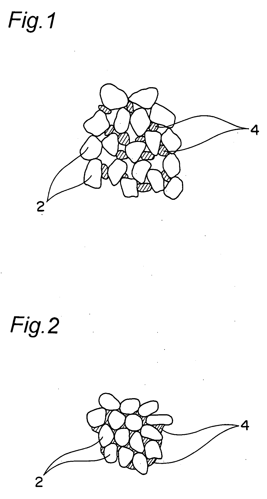
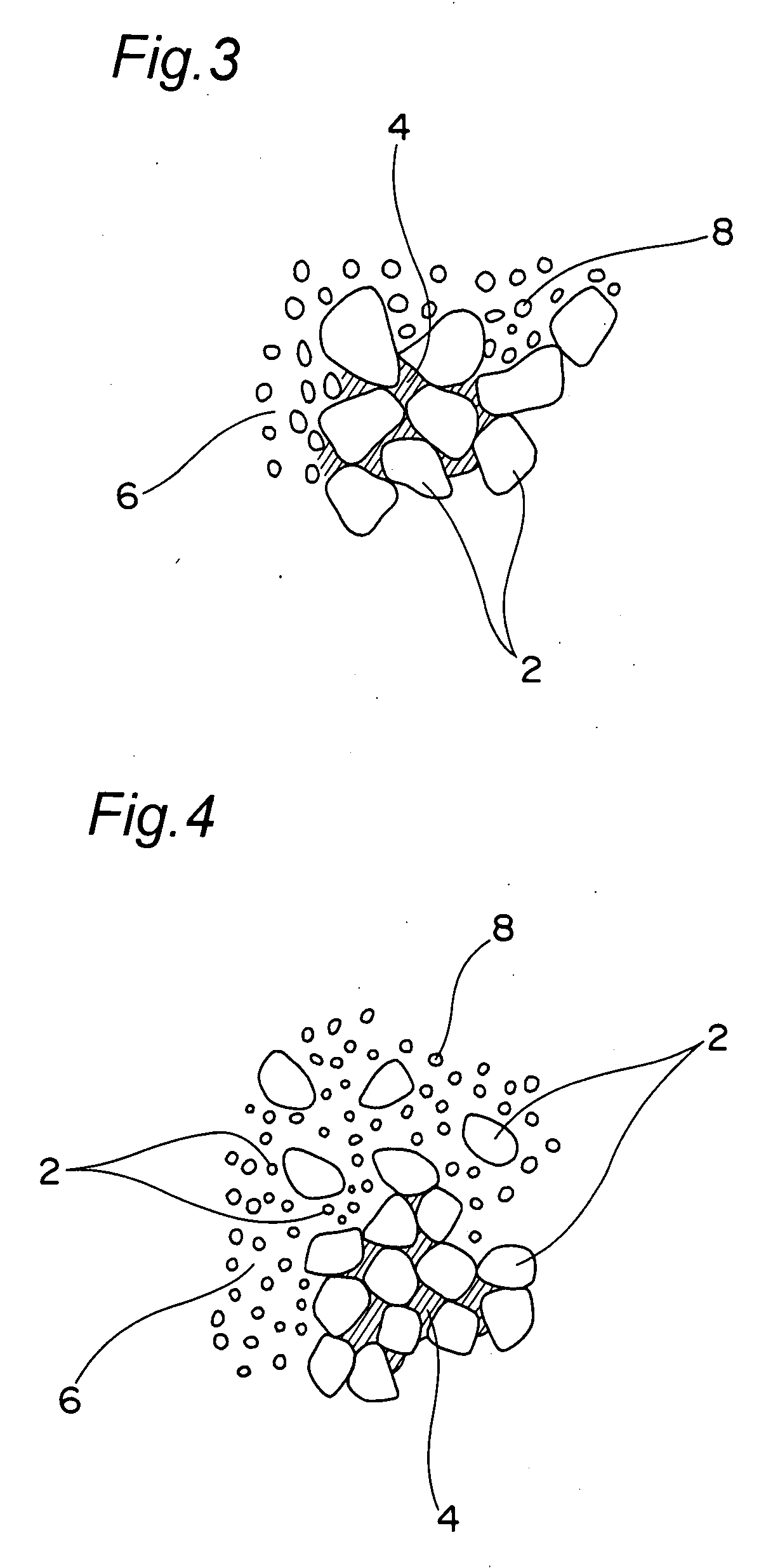
[0065]FIG. 1 depicts a magnetic substance, in which powder particles have been compacted, for use in a method of making a resin-molded magnetic core part according to a first embodiment of the present invention. This magnetic substance includes a large number of powder particles 2 constituting magnetic powder and each coated with an insulating material, and a large number of binder particles 4 interposed (dispersed) between the powder particles 2.

[0066] A resin having a melting temperature lower than a predetermined injection molding temperature is used as the binder 4. The binder 4 is fused or softened by injection molding it at a predetermined temperature with a base resin containing magnetic powder coated with the insulating material. As shown in FIG. 2, the intervals between the magnetic powder particles 2 are shortened, and the compacted magnetic substance shrinks, resulting in an increase in the filling density.

[0067] Preferably, examples of the magnetic powder particles 2 i...

embodiment 2

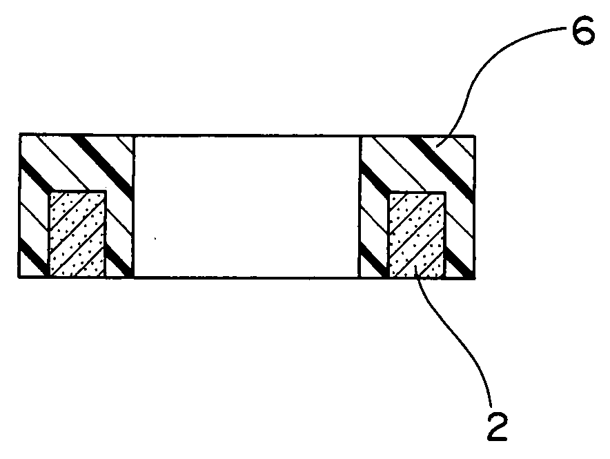
[0089]FIGS. 7A and 7B depict a magnetic core part made by a method of making a resin-molded magnetic core part according to a second embodiment of the present invention, wherein the magnetic core part is a coil-embedded magnetic part.

[0090] As shown in FIGS. 7A and 7B, under the condition in which opposite leading portions 12 of a coil 10 are caused to extend outwardly in the same direction in parallel to each other, a soft magnetic green compact 2 is first inserted inside the coil 10, and both of them are then insert molded into a resin composition 6 with only the opposite leading portions 12 exposed. By so doing, the permeability of the resin-molded magnetic core part is partially enhanced, thereby improving the performance thereof. In particular, if the soft magnetic green compact 2 is inserted inside the coil 10, the permeability on the inner side of the coil 10 is enhanced and, hence, not only can the coil diameter be reduced, but the number of turns can be also reduced.

[0091...

embodiment 3

[0092]FIGS. 9A and 9B depict a magnetic core part made by a method of making a resin-molded magnetic core part according to a third embodiment of the present invention, particularly depicting the case where the resin-molded magnetic core part is a coil-embedded magnetic part.

[0093] In the case of the resin-molded magnetic core part as shown in FIGS. 9A and 9B, a wire made of an electrically conductive material such as, for example, Cu is first wound around a generally straight bar (not shown) to form a coil 16, which is in turn pulled out of the bar and then curved so that the axial center of the coil 16 may present a generally circular shape with opposite leading portions 18 thereof led out in the same direction in parallel to each other. Thereafter, the curved coil 16 is insert molded into a resin composition 6 with only the opposite leading portions 18 exposed. This process makes it possible to considerably simply complete a toroidal core integrated with an air-core coil, as com...


PUM

PropertyMeasurementUnit
temperatureaaaaaaaaaa
magnetic propertiesaaaaaaaaaa
magneticaaaaaaaaaa

Abstract

Magnetic powder contained in a resin composition for use in injection molding is coated with an insulating material, and a soft magnetic green compact or a hard magnetic green compact is insert molded into the resin composition.

Description

TECHNICAL FIELD [0001] The present invention relates to a method of making a resin-molded magnetic core part for use in electronic instruments or electric instruments such as, for example, inductors, transformers, antennas (bar antennas), choke coils, filters, sensors, and the like. BACKGROUND ART [0002] In recent years, there is a growing tendency for an electronic or electric instrument to be reduced in size or increased in frequency or electric current and, hence, a core part is similarly required to respond to such tendency. However, ferrite material that is most frequently used now reaches a limit in terms of material characteristics, and a new material is being sought. In some cases, ferrite material is replaced with a new material such as, for example, Sendust or amorphous foil strip. Although amorphous powder material superior in magnetic properties appears, it is inferior in moldability or compactability to the conventional material, and the practical use thereof is accordi...

Claims


Application Information

Patent Timeline
Patent Type & Authority Applications(United States)
IPC IPC(8): H01F41/02
CPCB22F3/225B29C45/14778B29K2995/0008C22C2202/02H01F1/083H01F1/24H01F2017/048H01F17/045H01F17/062H01F27/027H01F27/255H01F41/005H01F41/0206H01F1/26H01F41/02B29C45/14
Inventor MATSUKAWA, KIYOTAKAISHIHARA, KOZOISHIKAWA, KAZUOTOYODA, TOMOHIROTANAKA, TOSHIKAZU
Owner NTN CORP
Why Eureka
Try Eureka