Residue Conditioning System

a technology of residue and conditioning system, which is applied in the details of gasification process, combustion process, combustible gas production, etc., can solve the problems of insufficient treatment of prior systems and processes, less desirable disposal of waste materials by incineration, and major problems in the disposal of solid waste, etc., to achieve the effect of optimizing the conversion reaction

Inactive Publication Date: 2007-11-08
PLASCO ENERGY GROUP INC
View PDF27 Cites 37 Cited by
  • Summary
  • Abstract
  • Description
  • Claims
  • Application Information

AI Technical Summary

Problems solved by technology

It is becoming less desirable to dispose of waste material by incineration because of the extreme waste of fuel in the heating process and the further waste of disposing, as a residual waste, material that can be converted into a useful syngas and solid material.
The gas produced during the gasification of carbonaceous feedstock is usually very hot but may contain small amounts of unwanted compounds and requires further treatment to convert it into a useable product.
Prior systems and processes have not adequately addressed the problems that must be dealt with on a continuously changing basis.
The disposal of solid waste has become a major issue due to space limitations for landfills and the environmental issues that arise.
Waste materials such as ash and slag are typically discarded in landfills, however, there is increasing public concern about gaseous emissions from landfills and the possibility of contamination of groundwater.

Method used


Image

  • Residue Conditioning System
  • Residue Conditioning System
  • Residue Conditioning System

Examples


examples

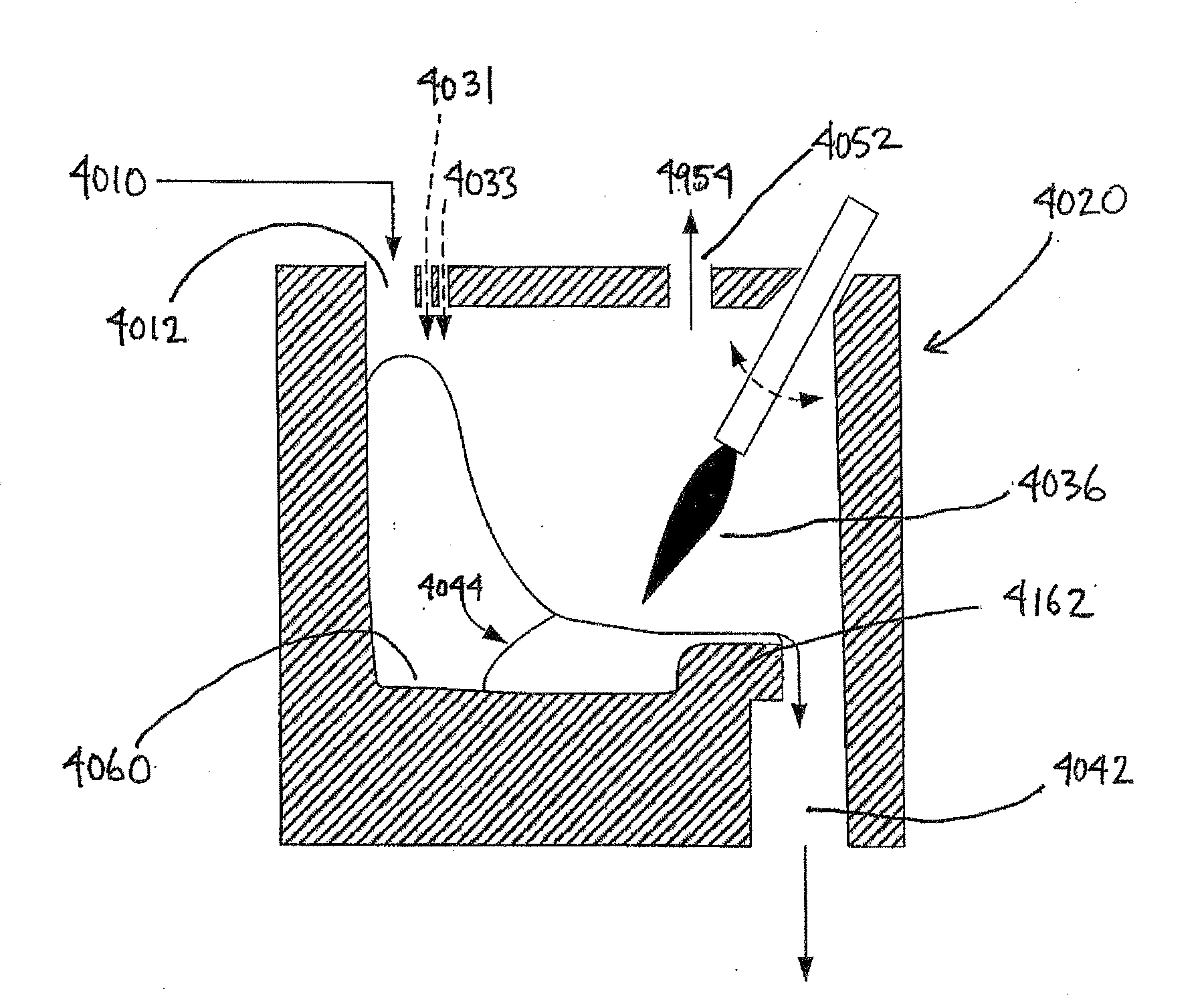
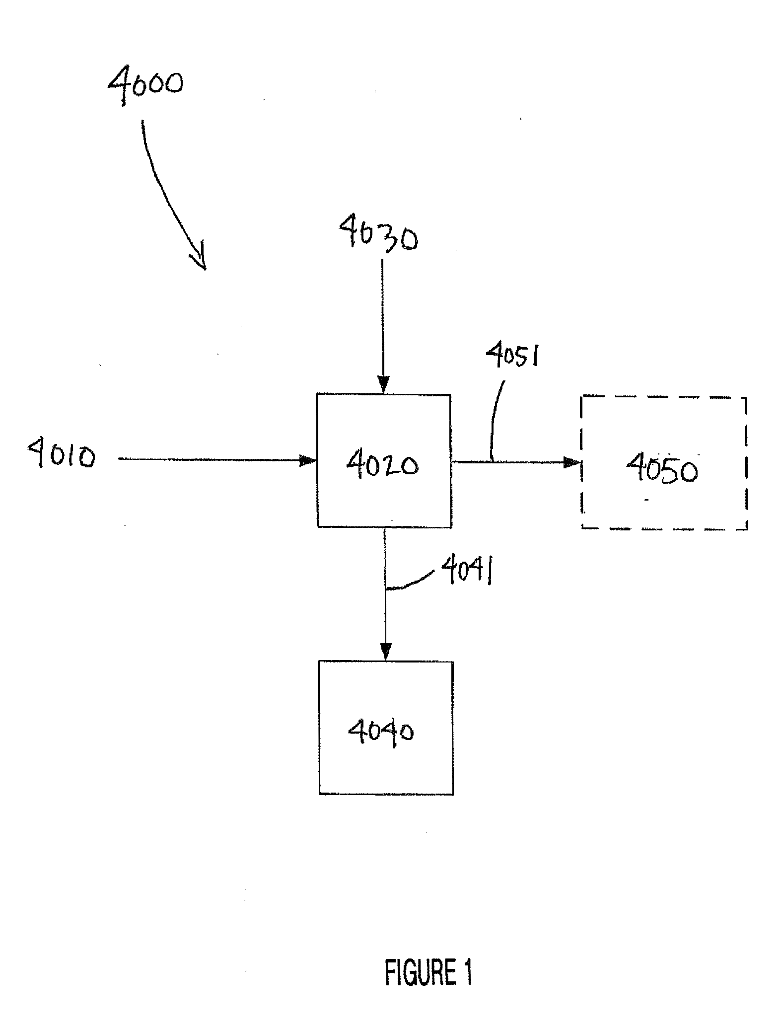
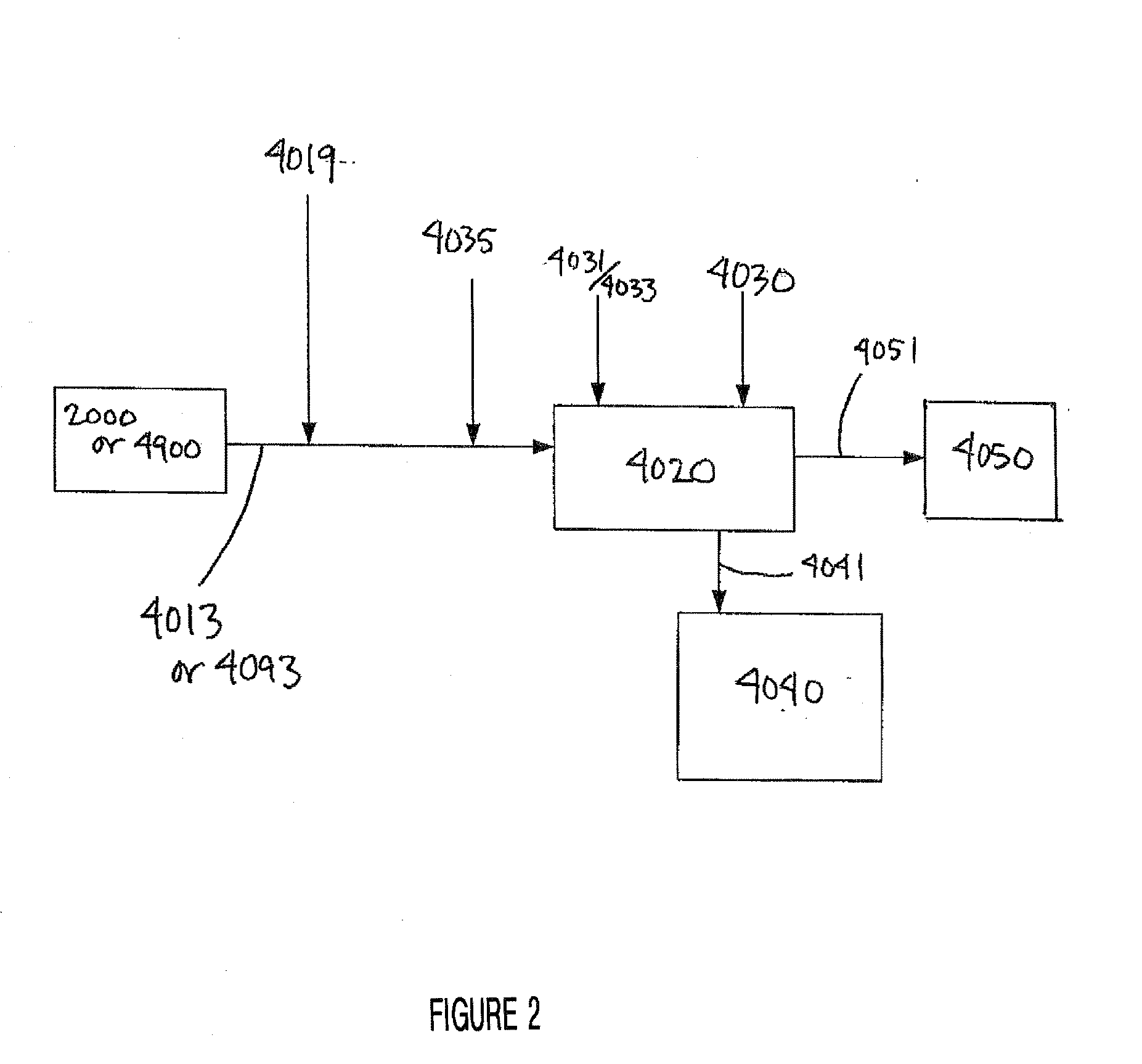
[0174] The present example is to provide an exemplary embodiment of the residue conditioning system of the present invention. Accordingly, the present example, as depicted in FIGS. 13 to 17, is provided to condition the residual matter produced in a typical gasification system during the gasification of carbonaceous feedstock. The sources of the residue to be conditioned are therefore the gasifier 2200 and the baghouse filter 6230 of a downstream gas conditioning subsystem of the gasification system. According to this example, the gasifier residue is removed from the gasifier 2200 by a first screw conveyor 2209 mounted at the end of the gasifier 2200. The first screw conveyor 2209 is provided as a toothed or serrated screw to break up agglomerated material. The residue is then conveyed via a gasifier residue screw conveyor 4218 to a main residue screw conveyor 4217. The baghouse residue is conveyed from the baghouse 6230 via a baghouse residue screw conveyor 4618 into the main resid...


PUM

PropertyMeasurementUnit
temperatureaaaaaaaaaa
pressuresaaaaaaaaaa
temperatureaaaaaaaaaa

Abstract

The present invention provides a system for converting the residue of a carbonaceous feedstock gasification or incineration process into an inert slag and a gas having a heating value. The residue is converted by plasma heating in a refractory-lined residue conditioning chamber. The gas produced is optionally passed through a gas conditioning system for cooling and cleaning to provide a product gas that is suitable for use in downstream applications. The system also comprises a control subsystem for optimizing the conversion reaction

Description

CROSS REFERENCE TO RELATED APPLICATIONS [0001] This application claims benefit of priority under 35 U.S.C. §119(e) from U.S. Provisional Application Ser. No. 60 / 746,628, filed May 5, 2006. This application also claims benefit of priority under 35 U.S.C. §119(e) from U.S. Provisional Application Ser. No. 60 / 864,116, filed Nov. 2, 2006. This application also claims benefit of priority under 35 U.S.C. §119(e) from U.S. Provisional Application Ser. No. 60 / 911,179, filed Apr. 11, 2007. This application also claims benefit of priority under 35 U.S.C. §119(e) from U.S. Provisional Application Ser. No. 60 / 797,973, filed May 5, 2006. The contents of all of the aforementioned applications are hereby expressly incorporated by reference in their entirety and for all purposes.FIELD OF THE INVENTION [0002] The present invention relates to systems for converting waste residue materials to an inert slag, and in particular to systems for the plasma assisted conversion of residual materials to an ine...

Claims


Application Information

Patent Timeline
Patent Type & Authority Applications(United States)
IPC IPC(8): B09B3/00F23G5/00C10J1/207
CPCC10J3/20Y02E20/18C10J3/723C10J3/82C10J3/84C10J2200/09C10J2300/0946C10J2300/1223C10J2300/1238C10J2300/1634C10J2300/1671C10J2300/1681F23G5/027F23G5/085F23G2204/201F23G2209/262F23J7/00F23J2219/70Y02E50/32Y02E20/12C10J3/482Y02E50/30
Inventor TSANGARIS, ANDREASSWAIN, MARGARET
Owner PLASCO ENERGY GROUP INC
Why Eureka
Try Eureka