Circuit board with heat radiating sheet

a technology of circuit boards and heat radiating sheets, which is applied in the direction of chemistry apparatus and processes, transportation and packaging, and other domestic objects, can solve the problems of circuit boards and electronic elements not maintaining at normal operating temperatures, changes in physical properties, and high temperature at some areas of circuit boards, so as to save time and labor costs for adding separate heat radiating sheets to electronic elements, and increase service life. the effect of heat generation

Inactive Publication Date: 2007-11-08
INSIGHT ELECTRONICS GROUP
View PDF3 Cites 14 Cited by
  • Summary
  • Abstract
  • Description
  • Claims
  • Application Information

AI Technical Summary

Benefits of technology

[0022]When the circuit board of the present invention is in use, the electronic elements mounted on the circuit board produce high amount of heat during operation thereof. The heat produced by the electronic elements is directly absorbed by the copper foil layer and then quickly transferred via the tin layer to the heat radiating sheet. Since the heat radiating sheet provides a larg

Problems solved by technology

However, the nowadays circuit boards have a large number of high-power electronic elements mounted thereon.
With the increased current supplied to the electronic elements, the power consumed by the electronic elements is increased at the same time to result in very high temperature at some areas on the circuit boards.
The high amount of heat produced by the large quantity of high-power electronic elements on a circuit board could not be completely radiated simply via conductive contact pins provided on the electronic elements, and the circuit board and the electronic elements fail to maintain at normal operating temperatures.
Exceeded operating temperatures would result in changes in the physical properties of the electronic elements to adversely affect the working performance, and risks of burnout and shortened service life of the electronic elements.
However, either the conventional circuit board or the above-described aluminum substrate has many disadvantages in term

Method used


Image

  • Circuit board with heat radiating sheet
  • Circuit board with heat radiating sheet
  • Circuit board with heat radiating sheet

Examples


Embodiment Construction

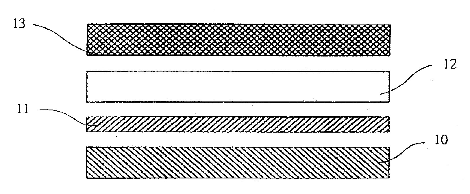
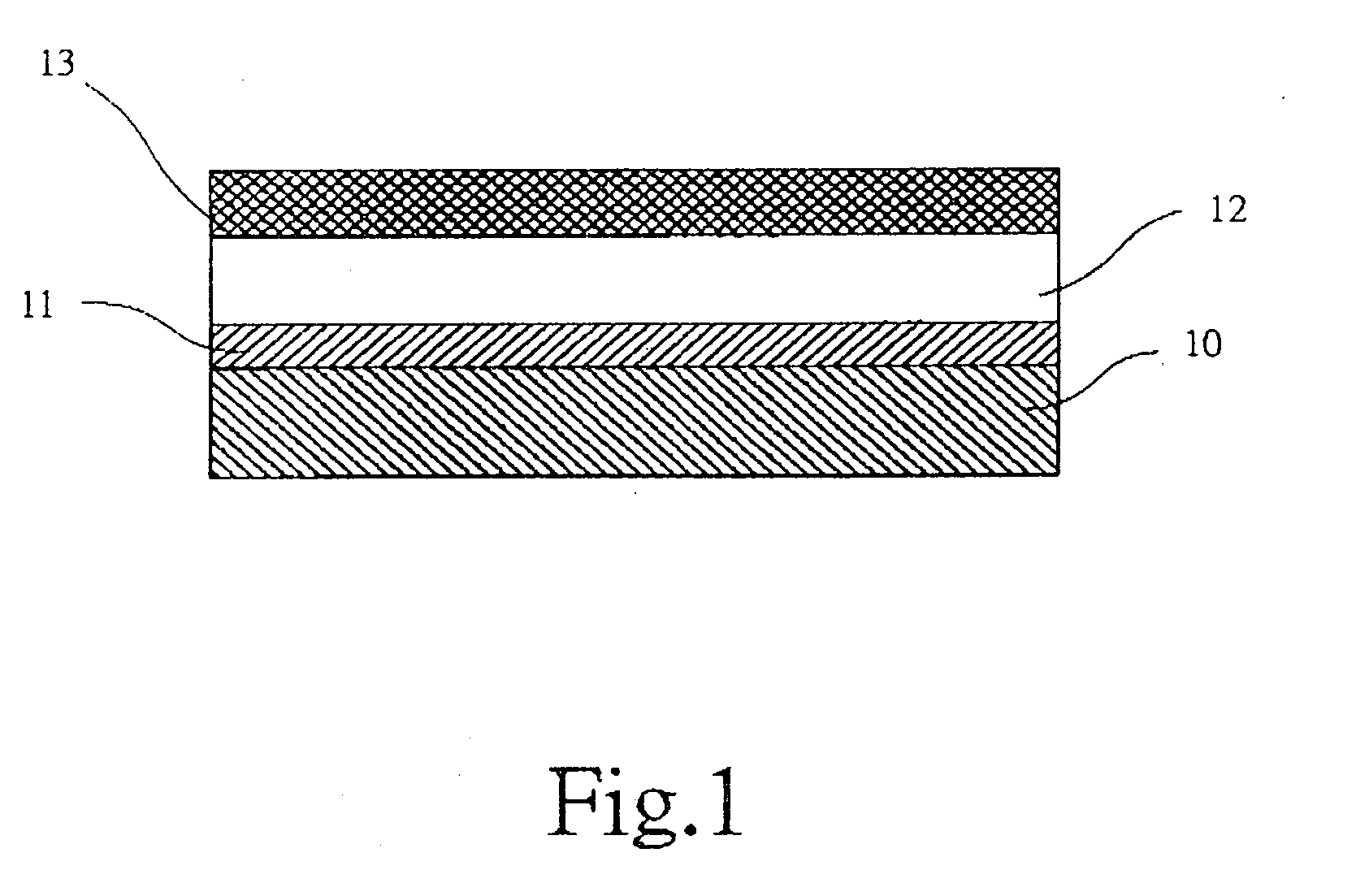
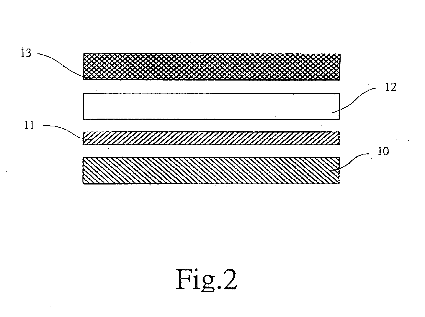
[0030]Please refer to FIGS. 1 and 2 that are assembled and exploded sectioned side views, respectively, of a circuit board with heat radiating sheet according to a first embodiment of the present invention. As shown, the first embodiment of the present invention includes a circuit board 10, a copper foil layer 11 formed on one surface of the circuit board 10, a tin layer 12 provided on a top of the copper foil layer 11, and a heat radiating sheet 13 associated with the tin layer 12.

[0031]The heat radiating sheet 13 may be made of a copper material, an iron material, or other suitable metal materials to enable enhanced heat conducting efficiency. When the heat radiating sheet 13 is made of an aluminum material, a layer of nickel must be plated on outer surfaces of the heat radiating sheet 13 to enable association of the aluminum material with the tin layer 12.

[0032]In one embodiment of the present invention, the circuit board 10 is a single-layer circuit board.

[0033]In another embodi...


PUM

PropertyMeasurementUnit
Temperatureaaaaaaaaaa
Flexibilityaaaaaaaaaa
Efficiencyaaaaaaaaaa

Abstract

A circuit board has a copper foil layer provided on one side thereof, a tin layer provided on a top of the copper foil layer, and a heat radiating sheet provided on the tin layer. When the circuit board is processed in a reflow oven, the tin layer is melted to associate with the copper foil layer and the heat radiating sheet. High amount of heat produced by electronic elements mounted on the circuit board during operation thereof is absorbed by the copper foil layer and then transmitted to the tin layer, which quickly transfers the absorbed heat to the heat radiating sheet that has a large radiating area, so that the heat is more quickly dissipated into air. A heat pipe may be embedded in the tin layer to enhance the radiating efficiency, so that the electronic elements on the circuit board always have a normal operating temperature.

Description

FIELD OF THE INVENTION[0001]The present invention relates to a circuit board with heat radiating sheet, and more particularly to a circuit board being provided with a tin layer on a copper foil layer thereof, and a heat radiating sheet and / or a heat pipe associated with the tin layer to provide increased heat dissipating area, so that heat produced by electronic elements mounted on the circuit board could be more quickly transferred to and dissipated from the heat radiating sheet into air.BACKGROUND OF THE INVENTION[0002]Circuit boards have wide applications in different fields. Electronic elements in most electronic products are mounted on a circuit board. Some of these electronic elements are high-power elements to produce high amount of heat during operation thereof. Therefore, currently available circuit boards are usually enhanced in design to enable quick heat dissipation therefrom.[0003]In the past, since only a small number of low power consumption electronic elements are mo...

Claims


Application Information

Patent Timeline
IPC IPC(8): B32B3/00
CPCB32B3/30B32B15/04B32B15/18B32B15/20Y10T428/24917H05K3/341B32B15/043B32B2307/30B32B2457/08H05K3/0061
Inventor HUANG, YU LI
Owner INSIGHT ELECTRONICS GROUP
Why Eureka
Try Eureka