Method for manufacturing a honeycomb structured body

a technology of structured body and honeycomb, which is applied in the direction of manufacturing tools, ceramicware, lighting and heating equipment, etc., can solve the problems of affecting the environment and the human body, containing soot and the like, and causing harm to the environmen

Inactive Publication Date: 2007-11-15
IBIDEN CO LTD
View PDF94 Cites 82 Cited by
  • Summary
  • Abstract
  • Description
  • Claims
  • Application Information

AI Technical Summary

Problems solved by technology

Particulates such as soot and the like contained in the exhaust gas expelled by the internal combustion engines of vehicles such as busses, trucks and the like, and construction equipment, have become a problem of recent, in that they cause harm to the environment and the human body.

Method used


Image

  • Method for manufacturing a honeycomb structured body
  • Method for manufacturing a honeycomb structured body
  • Method for manufacturing a honeycomb structured body

Examples


example 1

[0171] (1) 250 kg of α-type silicon carbide powder having a mean particle diameter of 10 μm, 100 kg of α-type silicon carbide powder having a mean particle diameter of 0.5 μm, and 20 kg of organic binder (methylcellulose) were mixed together to prepare a powder mixture.

[0172] Next, 12 kg of a lubricating agent (UNILUBE, manufactured by NOF Corp.), 5 kg of a plasticizer (glycerin), and 65 kg of water were mixed to separately prepare a liquid mixture. Next, using a wet mixer machine, the liquid mixture and the powder mixture were mixed together, thereby preparing the wet mixture.

[0173] Next, extrusion molding using the wet mixture followed by cutting was then carried out to produce honeycomb molded bodies. After that, the above mentioned honeycomb molded body was dried using a microwave drying apparatus.

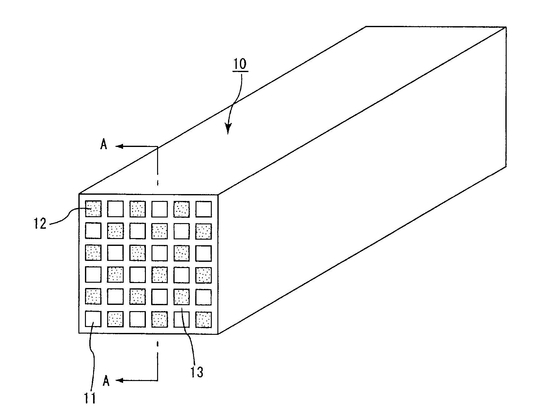
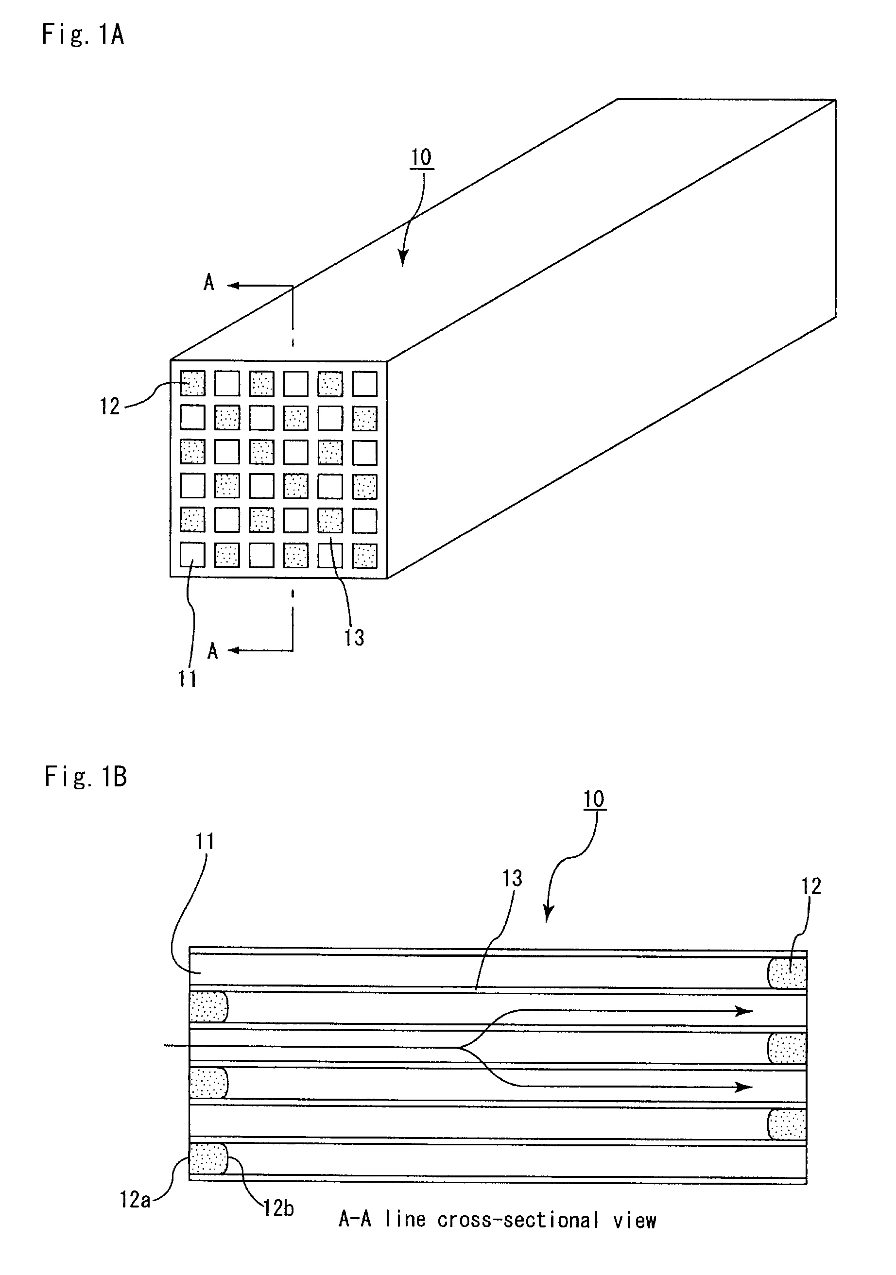
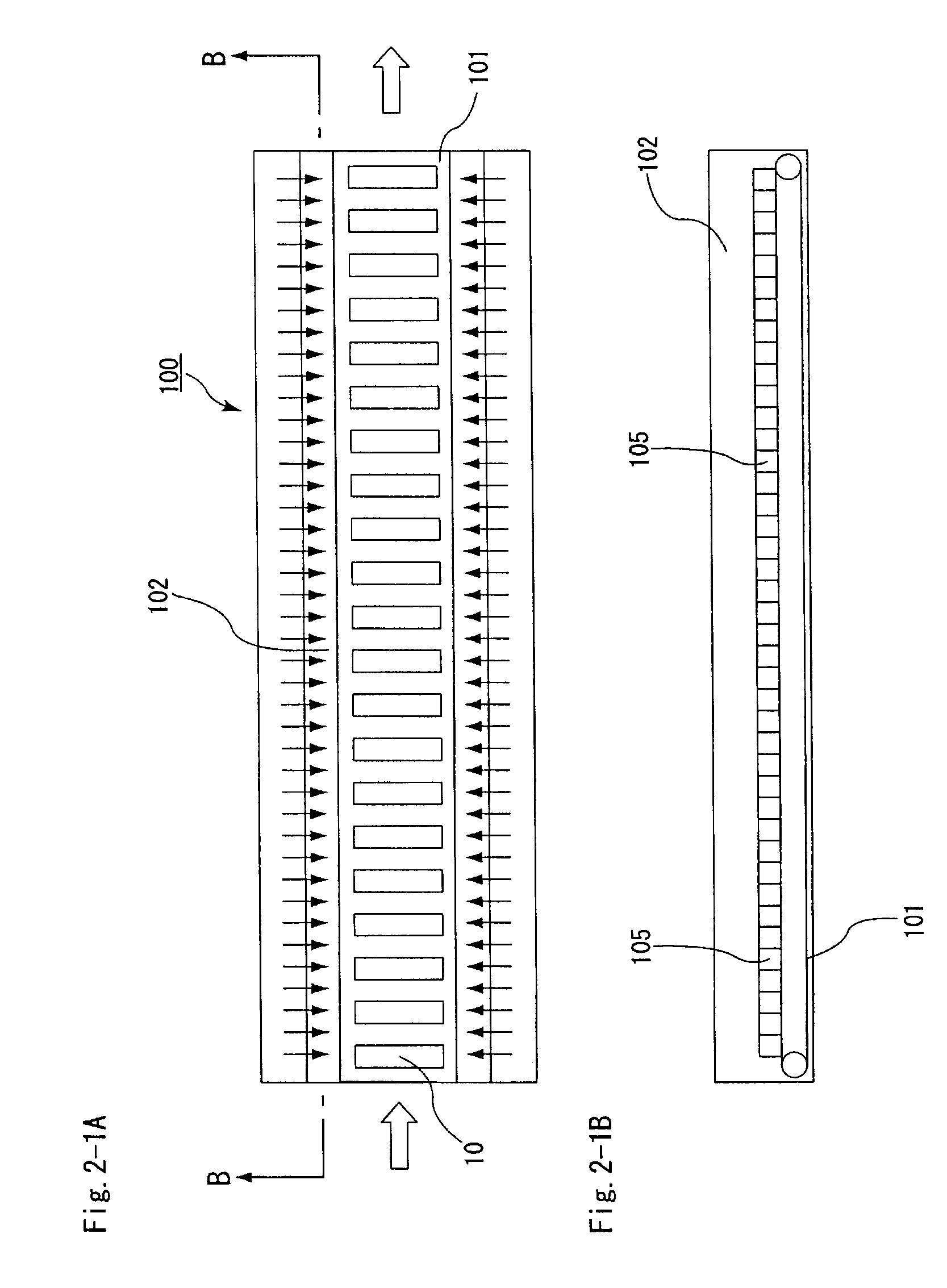
[0174] (2) Next, using a honeycomb molded body cell plugging apparatus having the structure shown in FIGS. 5, 6A, and 6B, prescribed cells were filled in with a plug material paste ...

examples 2 to 8

, Reference Examples 1 to 4

[0189] Aside from the point of having changed the temperature of the hot air and the time period over which the hot air is blown in the process (3) of Example 1 to the values indicated in Table 1, the honeycomb fired body was manufactured in the same manner as in Example 1.

example 9

[0190] Aside from the point of having changed the method by which hot air was blown to the end face of the honeycomb molded body in the process (3) of Example 1 to the following method, the honeycomb fired body was manufactured in the same manner as in Example 1.

[0191] Specifically, the plug material paste was dried by first blowing hot air from only the hot air blow ports on one side of the belt conveyer and also on ½ of the interior portion of the drying oven running from the inlet side, out of all of the hot air blow ports provided on both sides of the belt conveyer, and then blowing hot air from only the hot air blow ports on the side of the belt conveyer opposite to the hot air blow ports that blew hot air on the inlet side and also on ½ of the interior portion of the drying oven running from the outlet side.

[0192] Therefore, in the present example, hot air is blown to each of the end faces of the honeycomb molded body in turn.


PUM

PropertyMeasurementUnit
temperatureaaaaaaaaaa
speedaaaaaaaaaa

Abstract

A method for manufacturing a honeycomb structured body including molding ceramic raw material to form a pillar-shaped honeycomb molded body having a multiplicity of cells disposed in parallel with one another in the longitudinal direction with a cell wall therebetween, and filling in either one of the end portions of each of the cells with a plug material paste, and firing the honeycomb molded body to manufacture a honeycomb structured body comprising a honeycomb fired body, wherein after having filled in either one of the end portions of each of the cells of the honeycomb molded body with the plug material paste, a plug material paste drying process to dry the plug material paste is conducted by blowing hot air to an end face of the honeycomb molded body using a hot air drying apparatus.

Description

CROSS-REFERENCE TO RELATED APPLICATIONS [0001] This application claims priority of PCT / JP2006 / 308238 field on Apr. 19, 2006. The contents of this application are incorporated herein by reference in their entirety.BACKGROUND OF THE INVENTION [0002] 1. Field of the Invention [0003] The present invention relates to a method for manufacturing a honeycomb structured body. [0004] 2. Discussion of the Background [0005] Particulates such as soot and the like contained in the exhaust gas expelled by the internal combustion engines of vehicles such as busses, trucks and the like, and construction equipment, have become a problem of recent, in that they cause harm to the environment and the human body. To remedy this, there are currently being proposed numerous kinds of honeycomb filters using a honeycomb structured body of porous ceramic as a filter for capturing particulates contained in exhaust gasses, and thus purifying the exhaust gas. [0006] Conventionally, when manufacturing a honeycomb...

Claims


Application Information

Patent Timeline
Patent Type & Authority Applications(United States)
IPC IPC(8): C04B33/30
CPCB28B11/006B28B11/007F26B2210/02F26B21/022F26B21/006C04B2235/77C04B2235/767C04B2235/5472C04B2235/5445C04B2235/5436C04B2111/0081C04B2111/00793C04B38/0012C04B35/62655C04B35/565B28B11/243B28B17/0072B28B17/0081C04B35/00C04B38/0054C04B38/0074C04B38/085C04B38/0655C04B38/067C04B38/068
Inventor YAMAMURA, NORIHIKOHAYAKAWA, SYUHEIOHIRA, YOSHITERU
Owner IBIDEN CO LTD
Why Eureka
Try Eureka