Three-Dimensional, Ultrasonic Transducer Arrays, Methods of Making Ultrasonic Transducer Arrays, and Devices Including Ultrasonic Transducer Arrays

a technology of ultrasonic transducers and arrays, applied in the field of three-dimensional, ultrasonic transducer arrays, devices including transducers, can solve the problems of not seeing into the tissue, not seeing the surface of the gastrointestinal tract, and only providing two-dimensional images rather than real-time three-dimensional images

Active Publication Date: 2007-11-15
STC UNM
View PDF9 Cites 81 Cited by
  • Summary
  • Abstract
  • Description
  • Claims
  • Application Information

AI Technical Summary

Benefits of technology

[0013] In various aspects, the present disclosure is directed to medical imaging devices comprising an array of ultrasonic transducer elements. Each transducer element may comprise a substrate having a doped surface creating a highly conducting surface layer, a plurality of sandwiched dielectric layers, a first layer of conducting thin film on the dielectric layers, and a second layer of conducting thin film. The first layer of conducting thin film and the substrate may sandwich the dielectric layers. The second layer of conducting thin film may have a portion in contact with the first layer of conducting thin film and a portion separated from the first layer of conducting thin film, said second layer having at least one hole therethrough. A vacuum cavity may be between the first and second layers of conducting thin film. Each element may include a silicon nitride film on the second layer of conducting thin film, with the silicon nitride film extending through the hole in the second layer and into the vacuum cavity so as to prevent portions of the second layer from collapsing the vacuum cavity and contacting the first layer.

Problems solved by technology

However, this piezoelectric transducer is limited to providing only two-dimensional images rather than real-time three-dimensional images as needed by many diagnostic processes.
Additionally, due to the difficulty of mounting multiple pieces of transducers on the front and the side of a catheter platform, commercial IVUS are typically equipped with either a side-looking imager or a front-looking imager, but not both.
Although Pillcam causes far less discomfort for the patient and can reach a much further extent than is capable by the traditional tube endoscope, it has three basic constraints.
First, it can only see the surface of the gastrointestinal tract and can not see into the tissue.
This limits its capability in determining the extent of a tumor or abnormality in the digestive organs.
Secondly, Pillcam cannot shoot images of the colon or rectum because of blockage of stool.
As a result, a colonscopy is need for diagnosing the disorders in the colon or rectum and the process is very discomfortable.
Thirdly, Pillcam has only one camera and can only look at one direction when it (randomly) travels through the digestive tract.
This could result in missing of critical images for a diagnosing process.

Method used


Image

  • Three-Dimensional, Ultrasonic Transducer Arrays, Methods of Making Ultrasonic Transducer Arrays, and Devices Including Ultrasonic Transducer Arrays
  • Three-Dimensional, Ultrasonic Transducer Arrays, Methods of Making Ultrasonic Transducer Arrays, and Devices Including Ultrasonic Transducer Arrays
  • Three-Dimensional, Ultrasonic Transducer Arrays, Methods of Making Ultrasonic Transducer Arrays, and Devices Including Ultrasonic Transducer Arrays

Examples


Embodiment Construction

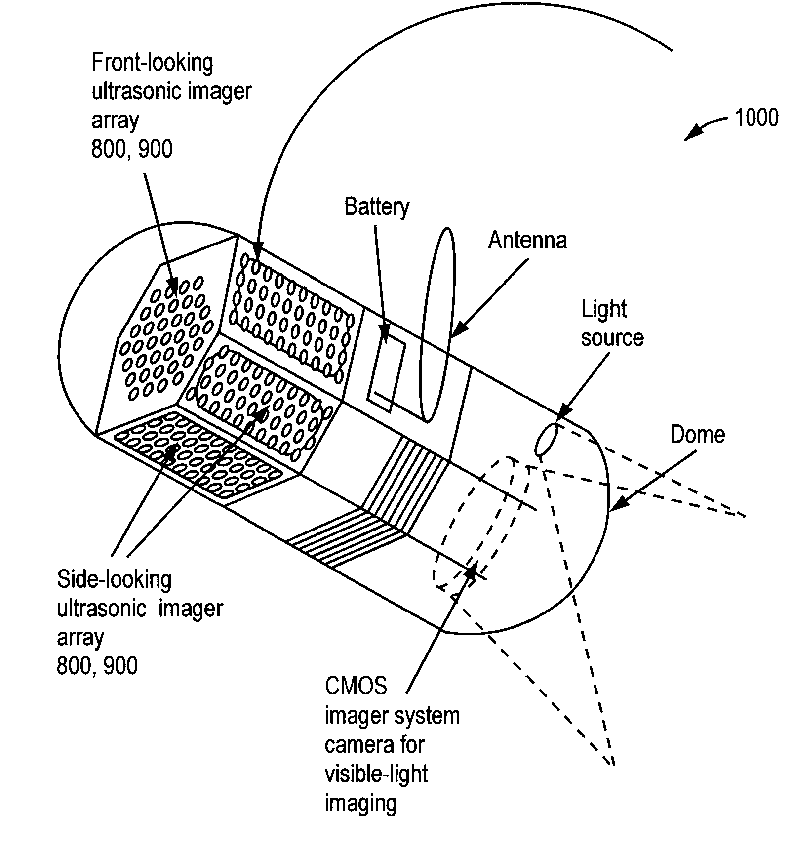
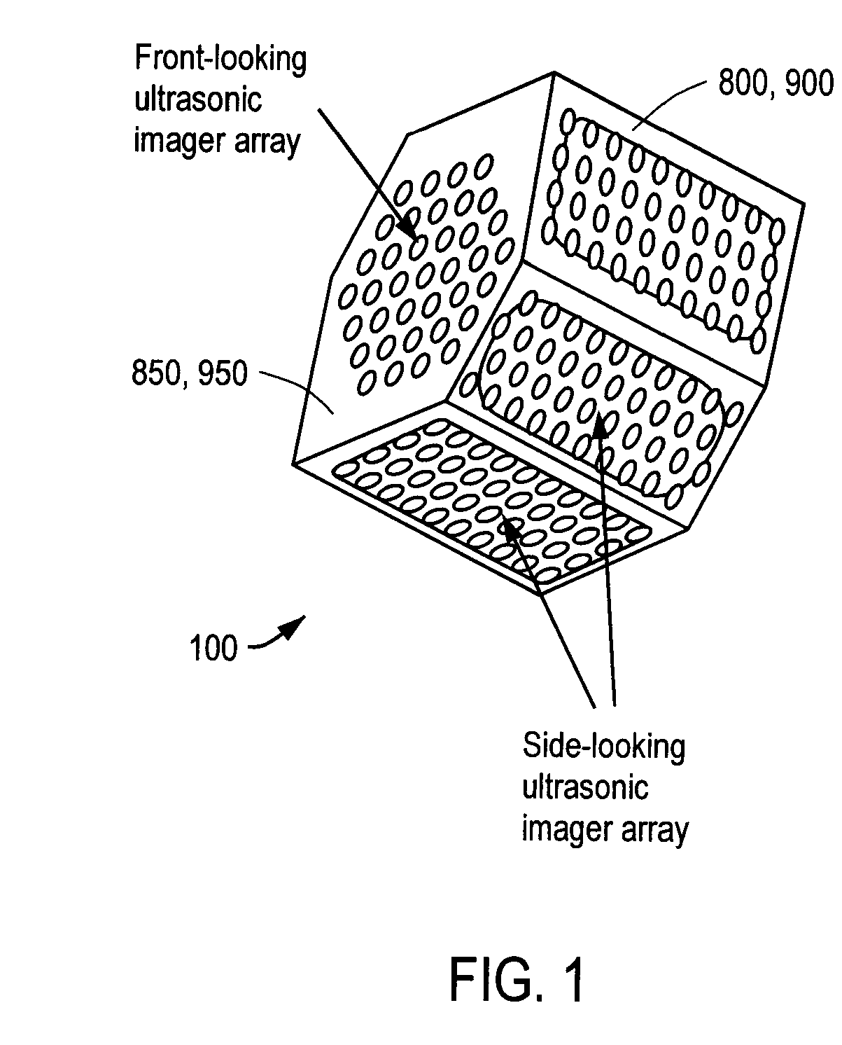
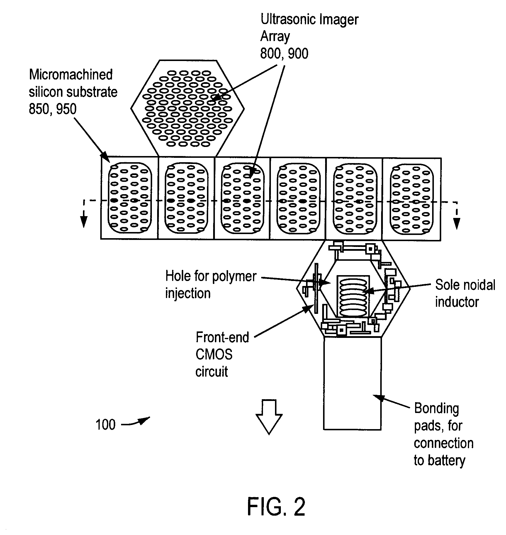
[0024] An exemplary embodiment of a monolithic multi-directional ultrasonic transducer array 100 is illustrated in FIGS. 1 and 2. According to some aspects, the transducer array 100 may comprise an imager array. The transducer array 100 may include integrated micro-machined (e.g., MEMS) ultrasonic transducers 800, 900 and front-end CMOS signal processing circuitry 120 on one piece of silicon substrate 850, 950. As a result of the monolithic structure, a better signal-to-noise ratio and therefore better image quality may be achieved by the imager array.

[0025] The exemplary monolithic ultrasonic imager array 100 may be divided into pieces of ultrasound-elements / CMOS-circuitry plates between which thin (1-20 μm thick) flexible silicon membranes are used for interconnection. These small plates, each typically measuring, for example, 0.8 millimeter×0.8 millimeter (for a 20 MHz ultrasonic imager) and 40 μm-100 μm thick, can be folded into a three-dimensional prism structure as shown in F...


PUM

PropertyMeasurementUnit
thickaaaaaaaaaa
thickaaaaaaaaaa
thickaaaaaaaaaa

Abstract

Medical imaging devices may comprise an array of ultrasonic transducer elements. Each transducer element may comprise a substrate having a doped surface creating a highly conducting surface layer, a layer of thermal oxide on the substrate, a layer of silicon nitride on the layer of thermal oxide, a layer of silicon dioxide on the layer of silicon nitride, and a layer of conducting thin film on the layer of silicon dioxide. The layers of silicon dioxide and thermal oxide may sandwich the layer of silicon nitride, and the layer of conducting thin film may be separated from the layer of silicon nitride by the layer of silicon dioxide.

Description

CROSS-REFERENCE TO RELATED APPLICATIONS [0001] This application claims the benefit of priority of U.S. provisional application No. 60 / 780,828, entitled “Wireless Multi-directional Capsule Endoscopes,” filed on Mar. 10, 2006, U.S. provisional patent application No. 60 / 804,018, entitled “Multi-directional Ultrasonic Imager Array,” filed on Jun. 6, 2006, and U.S. provisional application No. 60 / 836,162, entitled “Monolithic Three Dimensional Ultrasonic Transducer Array with Through-Wafer Electrical Interconnects,” filed on Aug. 7, 2006, the contents of all of which are incorporated herein by reference in their entirety.TECHNICAL FIELD [0002] The present invention is directed generally to transducer arrays, methods of making transducer arrays, and devices including transducer arrays. More particularly, the present invention is directed to three-dimensional, ultrasonic transducer arrays, methods of making ultrasonic transducer arrays, and medical devices including ultrasonic transducer ar...

Claims


Application Information

Patent Timeline
Patent Type & Authority Applications(United States)
IPC IPC(8): H01L21/00
CPCA61B1/041A61B8/12A61B8/4472A61B8/4488B06B1/0292Y10T29/42B81C1/00095B81C3/008G01S15/8929B06B1/06B81B2201/0271A61B8/4494
Inventor CHEN, JINGKUANG
Owner STC UNM
Why Eureka
Try Eureka