Power supply control circuit, and electronic control device, power supplying circuit, and power control integrated circuit equipped with power supply control circuit

a technology of power supply control circuit and control circuit, which is applied in the direction of emergency protective circuit arrangement, and pulse automatic control, etc., can solve the problems of electronic equipment arranged in electronic equipment that may be damaged, electronic equipment that may break, and the possibility of mos-fet 61/b> being damaged, etc., to prevent the breakdown of internal circuits, suppress the heat generation of switching elements, and prevent the effect of switching element breakdown

Active Publication Date: 2007-11-22
FUJITSU GENERAL LTD
View PDF8 Cites 42 Cited by
  • Summary
  • Abstract
  • Description
  • Claims
  • Application Information

AI Technical Summary

Benefits of technology

[0020]In view of the problems of the prior art, the present invention aims to provide a power supply control circuit capable of preventing breakdown of internal circuits even when the polarity of the power supply device is mistakenly connected, and suppressing heat generation of the switching element due to negative surge voltage to prevent breakdown of the switching element; and an electronic control device, a power supplying circuit, and a power supply control integrated circuit equipped with the power supply control circuit.

Problems solved by technology

When the polarity of the DC power supply such as battery is reverse connected by mistake in supplying power to electronic equipment such as an electronic control device mounted on the vehicle, the elements arranged in the electronic equipment may be damaged and the electronic equipment may breakdown.
However, even with the configuration shown in FIG. 1C, if a negative surge voltage that attempts to flow large current to the power supply line is generated when the MOS-FET 61 is in the OFF state, the possibility of the MOS-FET 61 being damaged is high since the withstanding voltage of the reverse voltage of the body diode D300 of the MOS-FET 61 is low compared to a commonly used stand-alone diode.
However, the following problems arise even if the active clamp circuit described above is used.
Therefore, if the negative surge voltage is applied when using the power supply device, a large potential difference determined by the reverse bias voltage of the Zener diode configuring the active clamp circuit is created between the drain and the source of the MOS-FET, and thus the power consumption of the MOS-FET becomes large, that is, the heat generation becomes large due to the potential difference.
One factor that further adds to the problem of heat generation is field decay surge.
Since a great number of inductive loads of motor, solenoid coil, and the like that drives each part of the vehicle such as electrically operated power steering and wipers are arranged in the vehicle, the generation of the field decay surge is inevitable when the switch with respect to the inductive load that is being supplied with power from the power supply device is turned OFF.
That is, the field decay surge is generated when the switch with respect to the inductive load in an electrically conducting state is turned OFF, whereby the frequency of occurrence becomes higher than other surge voltages such as surge voltage resulting from ESD (Electrostatic discharge) and surge voltage flowing from other power supply systems, which adds to the problem of heat generation.
In consequence, the efficiency may lower due to heat loss of the power supplied from the power supply device and failure of the power supply device may arise.

Method used


Image

  • Power supply control circuit, and electronic control device, power supplying circuit, and power control integrated circuit equipped with power supply control circuit
  • Power supply control circuit, and electronic control device, power supplying circuit, and power control integrated circuit equipped with power supply control circuit
  • Power supply control circuit, and electronic control device, power supplying circuit, and power control integrated circuit equipped with power supply control circuit

Examples


first embodiment

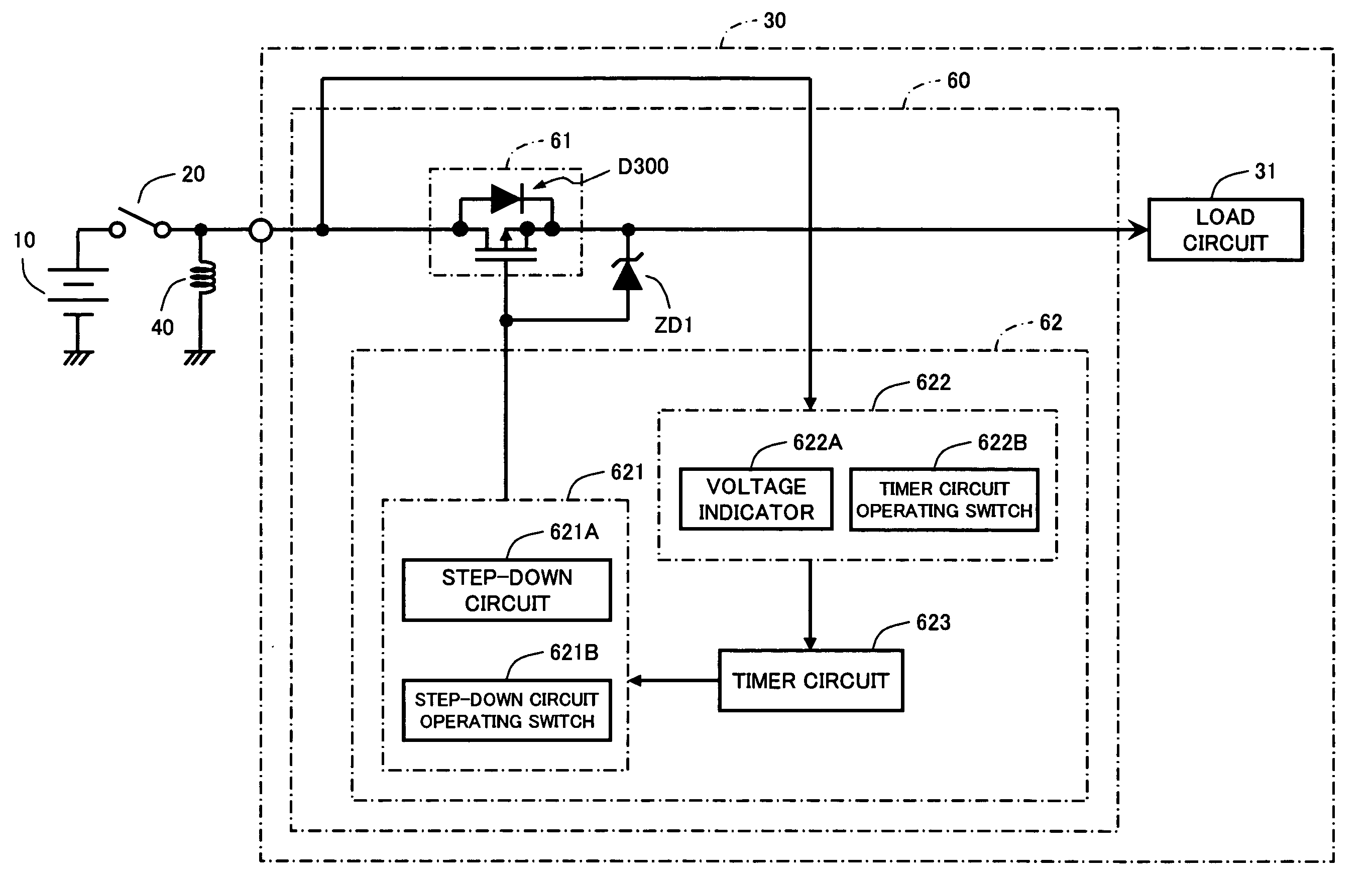
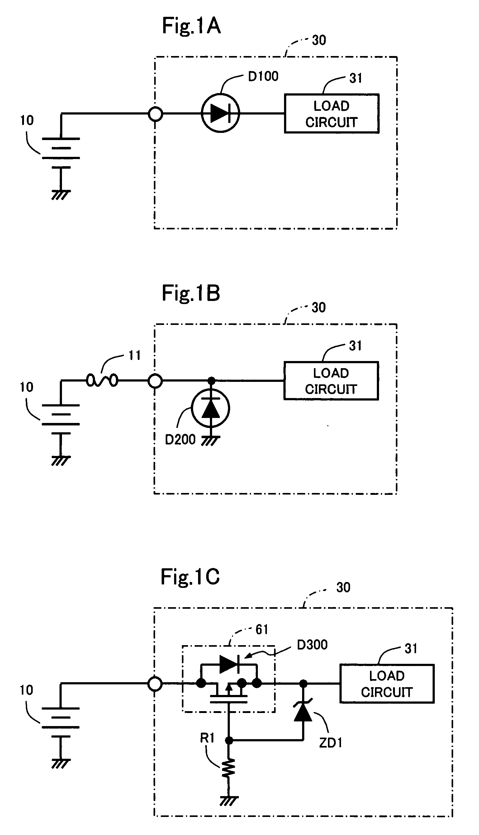
[0045]As shown in FIG. 3, the power supply control circuit 60 is configured including a p-channel enhancement type MOS-FET 61 connected between the DC power supply 10 and the load circuit 31 so that a body diode D300 formed between the drain and the source is forward biased; a holding circuit 62 for maintaining the ON state of the MOS-FET 61 for a predetermined time when the power supply from the DC power supply 10 is stopped; and a Zener diode ZD1 arranged between the gate and the source of the MOS-FET 61, the anode being connected to the gate and the cathode being connected to the source.

[0046]The operations of the MOS-FET 61 and the Zener diode ZD1 will be described in detail below. The Zener voltage of the Zener diode ZD1 is set lower than the voltage of the DC power supply 10. When the DC power supply 10 is connected at the correct polarity, the reverse bias voltage is applied to the Zener diode ZD1 via the body diode D300, whereby the gate voltage of the MOS-FET 61 has a pote...

third embodiment

[0070]The power supply control circuit 60 is configured including an active clamp circuit 64 for ON operating a MOS-FET 61 by the surge voltage generated when the power supply from the DC power supply 10 is stopped. As shown in FIG. 8, the active clamp circuit 64 includes a diode D1 for preventing backflow of the current and a Zener diode ZD3 for determining the operating voltage of the active clamp circuit 64, which are both connected in series between the gate and the drain of the MOS-FET 61. The cathode of the diode D1 is connected to the drain of the MOS-FET 61, the anode of the diode D1 is connected to the anode of the Zener diode ZD3, and the cathode of the Zener diode ZD3 is connected to the gate of the MOS-FET 61.

[0071]The operation of the active clamp circuit 64 described above will be described in detail below. When the negative surge voltage is applied to the power supply control circuit 60, if the negative surge voltage is smaller than the Zener voltage of the Zener dio...

fourth embodiment

[0073]The power supply control circuit 60 is configured by further including at the post-stage of the MOS-FET 61 a diode D2 for by-passing the surge current generated when the power supply from the DC power supply 10 is stopped. As shown in FIG. 9, the cathode of the diode D2, which anode is earth grounded, is connected to the source of the MOS-FET 61, that is, the diode D2 is connected in parallel at the post-stage of the MOS-FET 61. If the negative surge current is generated, the reverse current flows in a direction from the load circuit 31 towards the DC power supply 10, but a large portion of the reverse current flows through the diode D2 instead of through the load circuit 31 by connecting the diode D2.

[0074]The element of the load circuit 31 may breakdown if the reverse current flows through the load circuit 31, but the flow of large amount of current to the load circuit 31 can be inhibited and the breakdown of the load circuit 31 can be prevented with the configuration descr...


PUM


Abstract

A power supply control circuit is configured including a MOS-FET 61 connected between a DC power supply 10 and a load circuit 31 so that a body diode D300 formed between the drain and the source is in a forward direction; and a holding circuit 62 for maintaining the ON state of the MOS-FET 61 for a predetermined time when the power supply from the DC power supply 10 is stopped; where heat generation of the switching element by the surge voltage is suppressed when the surge voltage is generated to prevent breakdown of the switching element while preventing breakdown of internal circuits with respect to reverse connection of the power supply.

Description

BACKGROUND OF THE INVENTION[0001]1. Field of the Invention[0002]The present invention relates to a power supply control circuit including a MOS-FET connected between a DC power supply and a load circuit and connected so that a body diode formed between the drain and the source is in the forward direction, and a holding circuit for maintaining the ON state of the MOS-FET for a predetermined time when the power supply from the DC power supply is stopped; and an electronic control device, a power supplying circuit, and a power supply control integrated circuit equipped with the power supply control circuit.[0003]2. Description of the Related Art[0004]When the polarity of the DC power supply such as battery is reverse connected by mistake in supplying power to electronic equipment such as an electronic control device mounted on the vehicle, the elements arranged in the electronic equipment may be damaged and the electronic equipment may breakdown. A protective circuit has been conventio...

Claims


Application Information

Patent Timeline
Patent Type & Authority Applications(United States)
IPC IPC(8): H03L7/00
CPCH02H11/003H03K17/0822H03K17/08104H02M1/32
Inventor KOMATSU, KAZUHIROSHIMIZU, YUICHIROENOMOTO, DAISUKE
Owner FUJITSU GENERAL LTD
Why Eureka
Try Eureka