
Emission Treatment System with NSR and SCR Catalysts

a technology of emission treatment system and catalyst, which is applied in the direction of machines/engines, mechanical equipment, separation processes, etc., can solve the problems of nox species reduction, difficult to achieve effective abatement of nox from lean burn engines, and large etc., to achieve the effect of reducing the size and amount of particulate matter

Active Publication Date: 2007-11-22
BASF CORP
View PDF36 Cites 61 Cited by
  • Summary
  • Abstract
  • Description
  • Claims
  • Application Information

AI Technical Summary

Benefits of technology

This system achieves efficient and predictable NH3 formation during rich periods, enabling effective NOx treatment during lean periods, accommodating a broader range of operating conditions and reducing the need for external NH3 sources, thus enhancing NOx abatement capabilities.

Problems solved by technology

However, exhaust from lean burn gasoline engines is characterized by relatively high emissions of NOx as compared to conventional gasoline engines that operate at or close to stoichiometric air / fuel conditions.
Effective abatement of NOx from lean burn engines is difficult to achieve because high NOx conversion rates typically require reductant-rich conditions.
This step may recover some NOx storage sites but does not contribute to any reduction of NOx species.
However, the efficient reduction of released NOx by CO requires rich conditions.
A temperature surge can also trigger NOx release because metal nitrate is less stable at higher temperatures.
Urea, which upon hydrolysis produces ammonia, is injected into the exhaust in front of an SCR catalyst in the temperature range 200-600° C. One of the major disadvantages for this technology is the need for an extra large reservoir to house the urea on board the vehicle.
A problem associated with methods that utilize a portion of the NOx in the exhaust gas as an NH3 precursor is that, depending on operating conditions, insufficient NH3 is synthesized during rich operating periods to treat the NOx during lean periods (i.e., when the exhaust gas composition has a λ>1).
Therefore, less NH3 precursor is available for forming NH3 to treat a higher concentration of NOx that passes through the treatment system in a subsequent lean exhaust period.
This deficiency can limit the range of operating conditions where NOx can be effectively treated by the emissions treatment system.

Method used


Image

  • Emission Treatment System with NSR and SCR Catalysts
  • Emission Treatment System with NSR and SCR Catalysts
  • Emission Treatment System with NSR and SCR Catalysts

Examples


example 1

Preparation of Catalyst Substrates (NSR Catalysts)

Catalyst A

[0105] The substrate consisted of cordierite. The bottom layer consisted of 75 g / ft3 platinum, 0.42 g / in3 BaO, 0.05 g / in3 ZrO2 and 1.83 g / in3 of a support consisting of CeO2-coated Al2O3. This support was prepared by the incipient wetness technique to allow 10 wt. % of CeO2 on the surface of the Al2O3. The support material was impregnated with amine solubilized platinum hydroxide to achieve the desired loading. The powder was then milled, in the presence of water, such that 90% of the particles had a particle size below 10 micrometers (i.e., d90<10 μ), thereby resulting in a high-solids slurry. During the milling process, barium acetate and zirconyl acetate dissolved in water were also added during the milling process.

[0106] The slurry of the bottom layer was then wash-coated on the cordierite substrate and the coated substrate was then dried at 110° C. for about one hour. Thereafter, the dried coated substrate was calc...

example 2

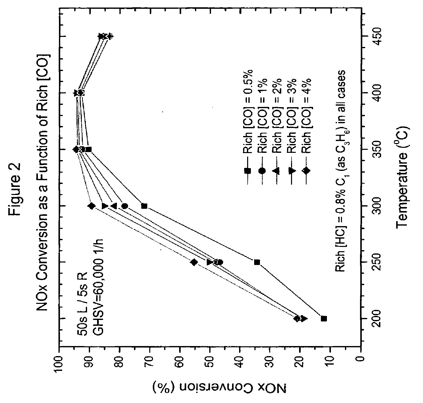
Performance Testing for Emissions Treatment Systems Having Catalyst A as an NSR Catalyst; Performance as a Function of CO Concentration in a Rich Feed

[0113] In this example, the NOx conversion, NH3 and N2 formation were determined as a function of the CO concentration in the rich pulse (i.e., in the rich gaseous stream). These determinations were first conducted with a system having in serial arrangement Catalyst A as the upstream substrate and a blank flow through monolith substrate as the downstream substrate. This system is referred to herein as “System I.”

[0114] A second system that was evaluated had in a serial arrangement, Catalyst A as the upstream substrate and SCR Catalyst D as the downstream substrate, which is referred to herein as “System II.” SCR catalyst D contained a catalyst composition with 1.8 g / in3 iron exchanged Beta zeolite with 4 wt. % ZrO2 binder that was coated onto a flow through monolith substrate.

[0115] Performance tests were conducted with an alternatin...

example 3

Performance Testing for Emissions Treatment Systems Having Catalyst A as an NSR Catalyst; Performance as a Function of Rich Feed Timing

[0117] In this example, the NOx conversion, NH3 and N2 formation were determined as a function of the rich feed timing. These determinations were first conducted with both System I and System II. System I and II are described in Example 2.

[0118] Performance tests were conducted with an alternating lean and rich feed. The lean feed consisted of 10% O2, 10% H2O, 5% CO2 and 200 ppm NO. The rich feed consisted of 0.8% HC (as C3H6), 1% O2, 10% H2O, 5% CO2, 200 ppm NO and 4% CO. The systems were evaluated at temperatures of 200, 250, 300, 350 and 450° C. with a GHSV of 60,000 h−1. In this test, the length of the rich pulse (rich period) was 1, 3 or 5 seconds while the lean period was always 50 seconds. Once the performance stabilized at a given temperature, data were collected for a period of 10 minutes. NO and NO2 concentrations (and therefore NOx conce...


PUM

PropertyMeasurementUnit
concentrationaaaaaaaaaa
temperatureaaaaaaaaaa
concentrationaaaaaaaaaa

Abstract

Provided is an emissions treatment system for an exhaust stream, having a NOx storage reduction (NSR) catalyst with a NOx sorbent at a concentration of at least 0.1 g / in3 and a platinum group metal component dispersed on a refractory metal oxide support; and, an SCR catalyst disposed downstream of the NSR catalyst. The emissions treatment system is advantageously used for the treatment of exhaust streams from diesel engines and lean burn gasoline engines.

Description

STATEMENT OF RELATED CASES [0001] This application is a continuation of applicant's U.S. patent application Ser. No. 10 / 975,428, filed Oct. 29, 2004, which claims priority from U.S. Provisional Patent Application Ser. No. 60 / 517,137, filed Nov. 4, 2003.[0002] The present invention relates to emissions treatment systems having NSR and SCR catalysts, and methods useful for reducing contaminants in exhaust gas streams, especially exhaust gas streams containing nitrogen oxides (NOx). More specifically, the present invention is concerned with improved NSR catalysts, emissions treatment systems and methods for their use with lean burn engines, including diesel engines and lean burn gasoline engines. [0003] Operation of lean burn engines, e.g., diesel engines and lean burn gasoline engines, provide the user with excellent fuel economy, and have very low emissions of gas phase hydrocarbons and carbon monoxide due to their operation at high air / fuel ratios under fuel lean conditions. Diesel ...

Claims


Application Information

Patent Timeline
Patent Type & Authority Applications(United States)
IPC IPC(8): B01D53/88F01N3/08B01D53/94F01N3/035F01N3/20F01N13/00
CPCB01D53/9418F01N13/009B01D53/9459B01D2255/202B01D2255/204B01D2255/2063B01D2255/2068B01D2255/20738B01D2255/20761B01D2255/50B01D2255/9022B01D2255/908B01D2255/91B01D2255/9155B01D2258/012F01N3/035F01N3/0814F01N3/0842F01N3/2073F01N2570/04F01N2570/16F01N2610/02F01N2610/03Y02T10/24F01N13/0093B01D53/9422Y02T10/12F01N3/08F01N3/20F01N3/10F01N13/00
Inventor LI, YUEJINDEEBA, MICHELDETTLING, JOSEPH CHARLESPATCHETT, JOSEPH ALLANROTH, STANLEY ALLEN
Owner BASF CORP
Learn More