Catalyst coated membrane, membrane electrode assembly containing the same, method of producing the same, and fuel cell including the membrane electrode assembly

a technology of membrane electrodes and catalysts, which is applied in the direction of electrochemical generators, cell components, coatings, etc., can solve the problems of insufficient utilization of the effect of increasing the loading concentration when using fuel cells with such supported catalysts, and the difficulty of producing electrodes containing an increased amount of supported catalysts, etc., to achieve maximum catalyst activity and enhance the performance of a unit cell

Inactive Publication Date: 2007-11-22
SAMSUNG SDI CO LTD
View PDF21 Cites 30 Cited by
  • Summary
  • Abstract
  • Description
  • Claims
  • Application Information

AI Technical Summary

Benefits of technology

[0010]An aspect of the present invention provides a catalyst coated membrane (CCM) which allows electrode catalyst layers to exhibit maximal catalyst activity and can enhance the performance of a unit cell, a membrane electrode assembly (MEA) including the catalyst coated membrane, and a method of producing the membrane electrode assembly.
[0011]Another aspect of the present invention also provides a fuel cell which employs the membrane electrode assembly and has improved power density and output voltage performance.

Problems solved by technology

It is also difficult to produce an electrode containing an increased amount of supported catalyst.
In the case of commercial Pt-supported catalysts, when the concentration of Pt metal particles in the supported catalyst is increased from 20% by weight to 60% by weight, the size of the Pt metal particles also increases by approximately four times. Thus, the effect of increasing the loading concentration cannot be fully utilized when such supported catalysts are actually used in fuel cells.
However, this method involving solvent reduction is disadvantageous in that the size of the catalytic metal particles varies depending on the type of the reducing agent, and the size of the catalytic metal particles also becomes too large at high loading concentrations of 30% by weight or greater.
Also, there still remains a problem in that the size of the catalytic metal particles increases as the loading concentration increases.

Method used


Image

  • Catalyst coated membrane, membrane electrode assembly containing the same, method of producing the same, and fuel cell including the membrane electrode assembly
  • Catalyst coated membrane, membrane electrode assembly containing the same, method of producing the same, and fuel cell including the membrane electrode assembly
  • Catalyst coated membrane, membrane electrode assembly containing the same, method of producing the same, and fuel cell including the membrane electrode assembly

Examples


example 1

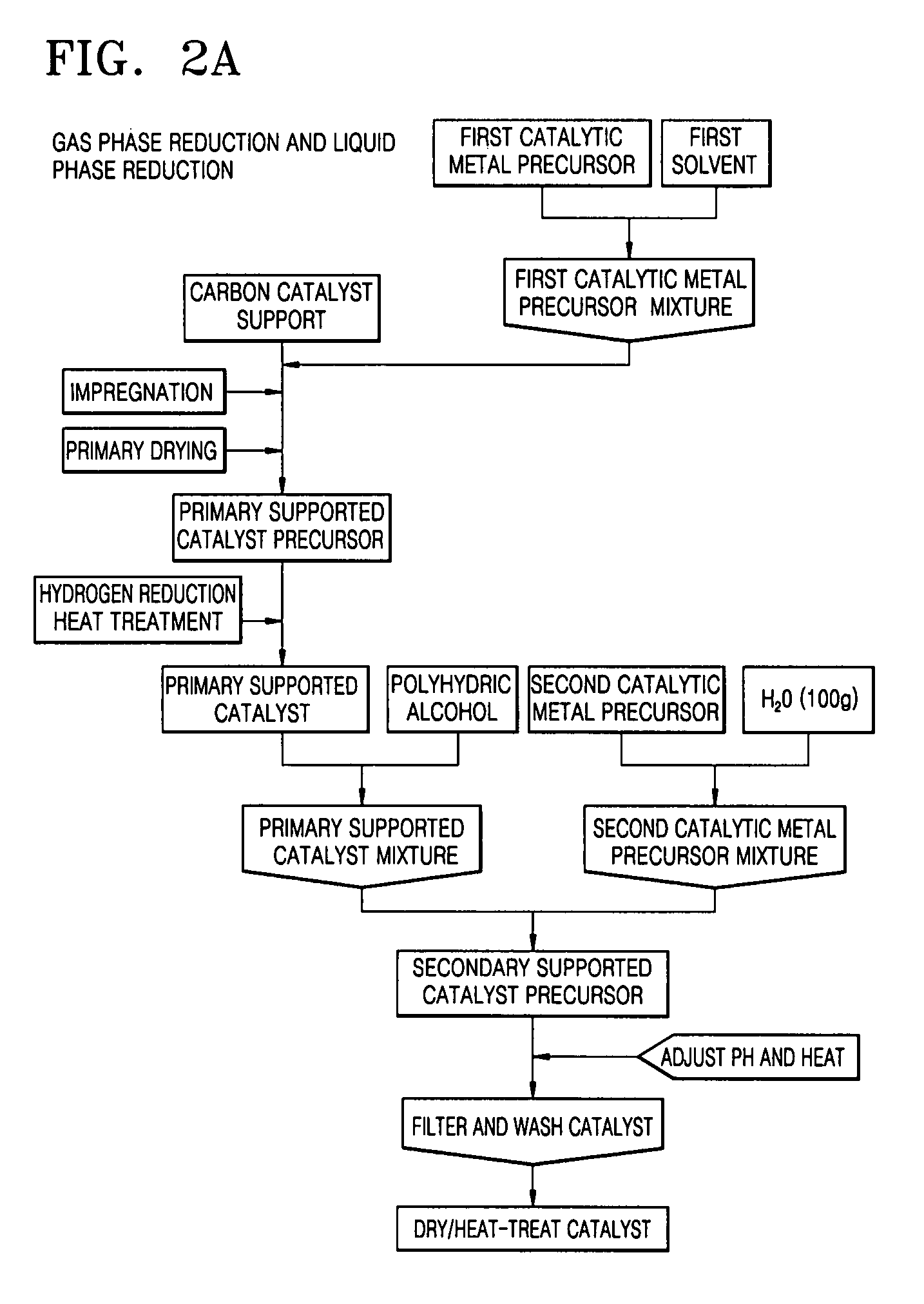
[0082]0.89 g of hexachloroplatinic acid (H2PtCl6.xH2O) and 0.40 g of ruthenium chloride (RuCl3.xH2O), which are catalytic metal precursors, were respectively dissolved in 2.5 ml of acetone and mixed to obtain a corresponding catalytic metal precursor mixture, and then 1 g of mesoporous carbon as a carbon support was impregnated with the catalytic metal precursor mixture in a plastic bag. The impregnated carbon support was placed in an electric furnace and subjected to a gas phase reduction reaction under a hydrogen gas stream to prepare a supported catalyst loaded with 35% by weight of PtRu (primary supported catalyst).

[0083]0.769 g of the first supported catalyst was added to 400 g of ethylene glycol to prepare a first supported catalyst mixture. Then, 1.516 g of hexachloroplatinic acid (H2PtCl6.xH2O) and 0.740 g of ruthenium chloride (RuCl3.xH2O), these amounts being 70% by weight of the final loading amount of catalytic metal, were dissolved in 200 g of triple-distilled water, an...

example 2

[0086]1.08 g of hexachloroplatinic acid (H2PtCl6.xH2O), which is a catalytic metal precursor, was dissolved in 6 ml of acetone to obtain a corresponding catalytic metal precursor mixture. Then, 1 g of mesoporous carbon as a carbon support was impregnated with the catalytic metal precursor mixture in a plastic bag. The impregnated carbon support was placed in an electric furnace and subjected to a gas phase reduction reaction under a hydrogen gas stream to prepare a supported catalyst loaded with 30% by weight of Pt (primary supported catalyst).

[0087]1.43 g of the primary supported catalyst was added to 260 g of ethylene glycol to prepare a primary supported catalyst mixture. Then, 2.692 g of hexachloroplatinic acid (H2PtCl6.xH2O), this amount being 60% by weight of the final loading amount of catalytic metal, was dissolved in 300 g of triple-distilled water, and the resulting solution was added to the first supported catalyst mixture. The pH of the resulting mixture was adjusted to ...

example 3

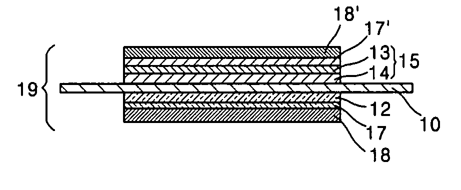
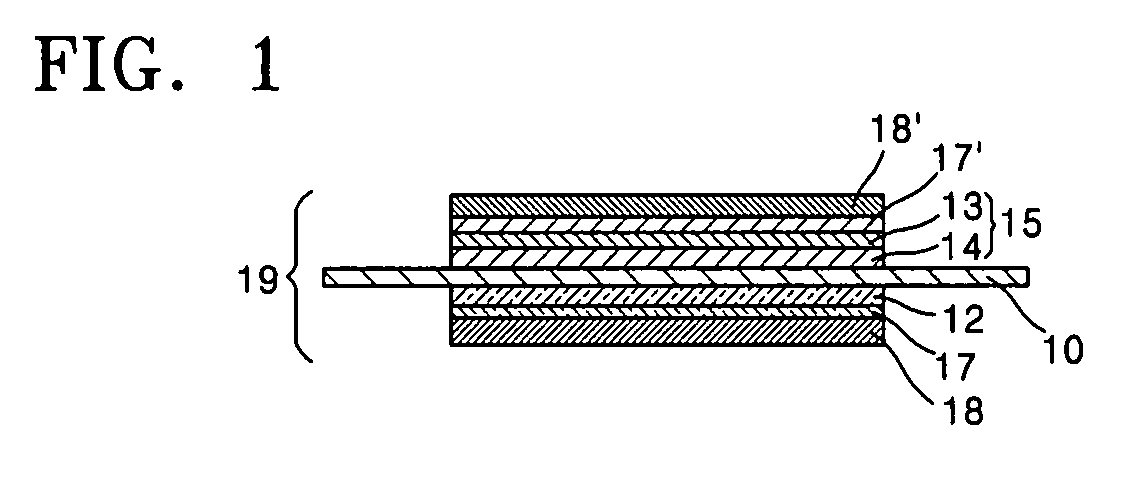
[0096]1.5 g of the 70 wt % PtRu / MC supported catalyst obtained in Example 1 was mixed with 2 g of deionized water, 1 g of ethylene glycol and 2.25 g of a 20 wt % NAFION® ionomer solution to prepare a slurry for forming a catalyst layer.

[0097]The slurry for forming a catalyst layer was bar coated onto a polyethylene film to a thickness of about 30 μm, and then the coating was dried in a vacuum oven at 80° C. to form a 70 wt % PtRu / MC supported catalyst layer.

[0098]Subsequently, a PtRu black non-supported catalyst layer was formed on top of the 70 wt % PtRu / MC supported catalyst layer to form an anode catalyst layer. Here, the PtRu black non-supported catalyst layer was formed as described below.

[0099]3 g of PtRu black was mixed with 3 g of deionized water, 2 g of ethylene glycol and 1.875 g of a 20 wt % NAFION® ionomer solution to prepare a slurry for forming a catalyst layer. The slurry for forming a catalyst layer was coated onto the 70 wt % PtRu / MC supported catalyst layer and dri...


PUM

PropertyMeasurementUnit
temperatureaaaaaaaaaa
thicknessaaaaaaaaaa
thicknessaaaaaaaaaa

Abstract

A catalyst coated membrane (CCM) comprising an anode catalyst layer having a first catalyst layer composed of a non-supported catalyst and a second catalyst layer composed of a supported catalyst, a cathode catalyst layer composed of a supported catalyst, and an electrolyte membrane interposed between the anode catalyst layer and a cathode catalyst layer, the first catalyst layer of the anode catalyst layer being disposed adjacent to the electrolyte membrane; a membrane electrode assembly (MEA) comprising the catalyst coated membrane; a method of preparing the membrane electrode assembly; and a fuel cell comprising the membrane electrode assembly, are provided. The CCM, which comprises a bilayered anode catalyst layer including the first catalyst layer composed of a non-supported catalyst and the second catalyst layer composed of a supported catalyst, exhibits reduced electrical resistance and interfacial resistance, and has increased catalyst availability. The use of the CCM and an MEA having the same results in a decrease in the interfacial resistance between the electrodes and the electrolyte membrane, a decrease in the amount of the catalyst used in the electrode catalyst layer, and a decrease in the thickness deviation in the electrode layers. The fuel cell employing the MEA exhibits maximal activity of the supported catalyst, and has improved cell characteristics such as output voltage, output density, efficiency, and the like.

Description

CROSS-REFERENCE TO RELATED APPLICATIONS[0001]This application claims the benefit of Korean Patent Application No. 2006-43941, filed May 16, 2006, in the Korean Intellectual Property Office, the disclosure of which is incorporated herein by reference.BACKGROUND OF THE INVENTION[0002]1. Field of the Invention[0003]Aspects of the present invention relate to a catalyst coated membrane (CCM), a membrane electrode assembly (MEA) containing the catalyst coated membrane, a method of preparing the catalyst coated membrane, and a fuel cell employing the membrane electrode assembly, and in particular, to a novel catalyst coated membrane employing a bilayered anode catalyst layer with improved catalyst activity, a membrane electrode assembly containing the catalyst coated membrane, a method of producing the catalyst coated membrane, and a fuel cell including the membrane electrode assembly.[0004]2. Description of the Related Art[0005]Active research is being conducted on electrodes, fuel, and e...

Claims


Application Information

Patent Timeline
Patent Type & Authority Applications(United States)
IPC IPC(8): H01M8/10
CPCH01M4/8657H01M4/8668H01M4/881H01M4/8814H01M4/8828Y02E60/50H01M4/8882H01M4/921H01M4/926H01M4/928H01M4/8875H01M4/86H01M4/88
Inventor PAK, CHAN-HOLEE, SEOL-AHCHANG, HYUKKIM, JI-RAEYOO, DAE-JONGJOO, SANG-HOON
Owner SAMSUNG SDI CO LTD
Why Eureka
Try Eureka