Methods for manufacturing heat sink having relatively high aspects ratio thereof

a technology of heat sink and aspect ratio, which is applied in the direction of manufacturing tools, semiconductor/solid-state device details, transportation and packaging, etc., can solve the problems of high defective rate of manufactured heat sink b>10/b>, time-consuming whole procedure, etc., and achieve high aspect ratio

Inactive Publication Date: 2007-11-29
MALICO
View PDF6 Cites 3 Cited by
  • Summary
  • Abstract
  • Description
  • Claims
  • Application Information

AI Technical Summary

Benefits of technology

[0015]It is therefore an object of the present invention to propose methods

Problems solved by technology

One with an ordinary skill in the field would know that the above-mentioned method has the drawbacks that relatively the m

Method used


Image

  • Methods for manufacturing heat sink having relatively high aspects ratio thereof
  • Methods for manufacturing heat sink having relatively high aspects ratio thereof
  • Methods for manufacturing heat sink having relatively high aspects ratio thereof

Examples


Embodiment Construction

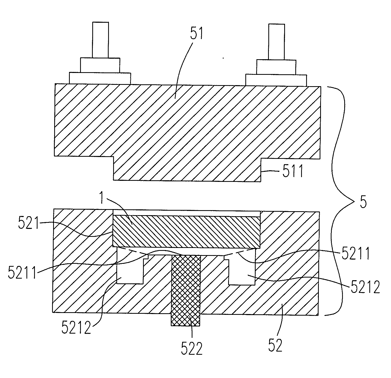
[0049]As aforementioned, the relatively better performance of the heat sinks could be achieved by increasing the aspect ratio of the heat sink through a tooling procedure for manufacturing the die 5 with a relatively high surface hardness, a specific inner hardness, a specific surface friction and a specific toughness so as to stand a relatively high pressure and achieve a relatively high aspect ratio of the heat sink 30 (see FIGS. 4(a)-4(d)).

[0050]Please refer to FIGS. 4(a)-4(d), the first proposed method for manufacturing a heat sink 30 having a central cavity 31, a taper core 32, a plurality of fins 33 and a base plate 34 integrally formed with the taper core 32 and the fins 33 includes the steps of: (a) making a die 5 having a relatively high surface hardness, a specific inner hardness, a specific surface friction and a specific toughness so as to stand a relatively high pressure and achieve a relatively high aspect ratio of the heat sink; (b) putting a material 1 into the die 5...


PUM

PropertyMeasurementUnit
Thicknessaaaaaaaaaa
Electrical conductivityaaaaaaaaaa
Ratioaaaaaaaaaa

Abstract

Methods for manufacturing a heat sink having a central cavity, a taper core, a plurality of fins and a base plate integrally formed with the taper core and the fins are provided. The first proposed method includes the steps of: (a) making a die having a relatively high surface hardness, a specific inner hardness, a specific surface friction and a specific toughness so as to stand a relatively high pressure and achieve a relatively high aspect ratio of the heat sink; (b) putting a material into the die; (c) pressing the material with the relatively high pressure to form the heat sink integrally such that the heat sink would have a relatively high material crystal density; and (d) removing the heat sink from the die.

Description

FIELD OF THE INVENTION[0001]The present invention relates to methods for manufacturing a heat sink having a central cavity, a core, a plurality of fins and a base plate and more particularly for manufacturing a heat sink having a central cavity, a taper core, a plurality of fins and a base plate integrally formed with the taper core and the fins with a relatively high aspect ratio.BACKGROUND OF THE INVENTION[0002]Due to the dramatically increasing requirements and higher standards in heat dissipation, a kind of heat sinks with a plurality of fins, a core, a central cavity and a base plate in contacting with a heat source, which could be an electronic component such as a CPU, are commonly used for properly dissipating the heat generated by the heat source nowadays (e.g., see U.S. Pat. No. 5,828,551). To further enhance the heat dissipation, heat sinks having the central portion of the base plate made of a relatively high conductivity material with larger thermal conductivity than tha...

Claims


Application Information

Patent Timeline
IPC IPC(8): B21D53/02
CPCB21K1/36B23P15/26B23P2700/10H01L21/4878Y10T29/4935H01L2924/0002H01L23/467Y10T29/49982H01L2924/00
Inventor LIANG, ROBERT
Owner MALICO
Why Eureka
Try Eureka