Apparatus for Treating Solutions of High Osmotic Strength

a technology of osmotic strength and apparatus, which is applied in the direction of filtration separation, multi-stage water/sewage treatment, separation process, etc., can solve the problems of shortening the life of spiral wound elements, reducing the utilization of membranes, and pressure dropping down vessels, so as to improve the utilization of pressure vessels and improve the effect of osmotic strength and uniform flux distribution

Inactive Publication Date: 2007-11-29
MICKOLS WILLIAM EDWARD +4
View PDF18 Cites 89 Cited by
  • Summary
  • Abstract
  • Description
  • Claims
  • Application Information

AI Technical Summary

Benefits of technology

[0022] This invention improves pressure vessels in membrane filtration systems for treating solutions of high osmotic strength, and is useful for seawater desalination systems. A given pressure vessel in the membrane filtration system contains at least three spiral wound elements with substantially differing standard specific fluxes, as described in more detail below, and, optionally, selec

Problems solved by technology

The decreased flux results in decreased utilization of membrane.
This problem is further aggravated by hydraulic resistance to feed flow within each element, resulting in a pressure drop down the vessel.
Higher initial flux can substantially shorten the life of a spiral wound element due to fouling and scaling.
High flux also promotes concentration polarization, decreasing the effective rejection of the membrane.
However, lower flux in downstream elements is also undesirable, because of decreased productivity; lower flux means higher solute concentration in the permeate, and therefore lower recoveries.
In addition to reducing production of permeate, flux imbalance contributes to fouling and decreases overall water quality due to polarization in the upstream elements and low flux in the downstream elements.
Finally, higher recoveries may reduce the volume of plant discharge.
The recoveries which can be obtained in a vessel, and the associated benefits, have conventionally been limited by the threats of fouling at the lead end and low flow (for both permeate and concentrate) at the tail end.
However, an increased number of elements generally results in the last elements in a vessel operating at very low flux; the resulting permeate quality is lower because less water passes through these last elements.
Additionally, the

Method used


Image

  • Apparatus for Treating Solutions of High Osmotic Strength
  • Apparatus for Treating Solutions of High Osmotic Strength
  • Apparatus for Treating Solutions of High Osmotic Strength

Examples


example 1

[0062] A membrane element was constructed using FILMTEC SW30HR membrane. Four elements having 2.6 m2 of active membrane area were constructed, using FILMTEC SW30SXLE membrane. Three of the SW30SXLE membrane elements were treated by immersing the membrane in an aqueous solution of 2000 ppm NaOCl for 30 minutes at pH was 10.5. Table 3 shows the measured standard specific flux and standard solute permeability for these elements.

TABLE 3Elements described in Example 1StandardSpecific FluxStandard SoluteL / m2 / PermeabilityElementMembranehr / bar(gfd / psi)L / m2 / hr(gfd)ASW30HR1.07(0.043)0.29(0.17)BSW30XLE1.43(0.058)0.45(0.26)CSW30XLE (treated)2.12(0.086)0.33(0.19)DSW30XLE (treated)1.85(0.075)0.32(0.19)ESW30XLE (treated)1.99(0.082)0.20(0.12)

[0063] Elements A, B, and C were loaded into a vessel, so that element A was in the lead the position and element C was in the tail position. Permeate flow was blocked between elements B and C to allow the permeate solution from element C to be collected sepa...

example 2

[0065] Two FILMTEC SW30XLE-380 elements were treated by immersing for 30 minutes in an aqueous solution of 1500 ppm and 2000 ppm, respectively, of NaOCl at pH 10.5. The elements had standard specific flux and standard solute permeability values shown in rows H and I of Table 4. In addition, the standard specific flux and standard solute permeability values of FILMTEC SW30HR-380 and SW30XLE-380 elements not contacted with NaOCl are shown in rows F and G, respectively. The ratio of standard solute permeability to standard specific flux for the tail element (0.064) divided by the ratio of standard solute permeability to standard specific flux for the lead element (0.071) is less than 1. For all elements in Table 4, the standard pressure gradient was approximately 0.2 bar / m, and the feed spacer cross sectional area was approximately 230 cm2.

TABLE 4Elements described in Example 2StandardStandard SoluteSpecific FluxPermeabilityElementNaOClL / m2 / hr / bar(gfd / psi)L / m2 / hr(gfd)F0ppm0.96(0.039)...

example 4

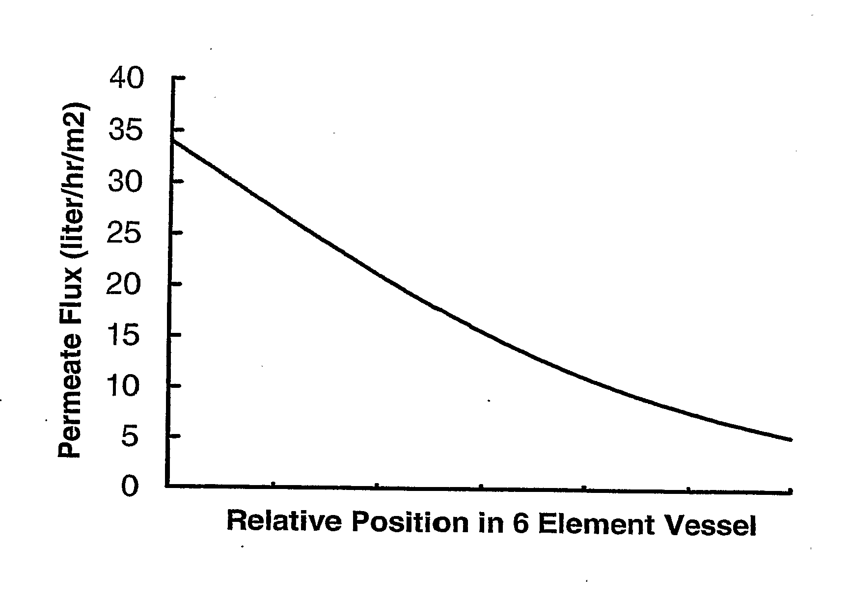
[0075] Calculations were performed as in Example 3, using a 167 m3 / day (44000 gpd) feed of 3.5% seawater. An applied pressure of 79.3 bar (1150 psi) resulted in a simulated recovery of 60.8% for this vessel. In this case, seven elements within the vessel potentially differed in A values, B values and active area, as noted in the table. The combined permeate concentration was estimated at 448 ppm. Simulations show each element within this vessel to have low values for maximum flux, average flux and element recovery. Dividing the total permeate flow by the active membrane area provides an average flux for the vessel of 18.8 L / m2 / hr (11.1 gfd).

TABLE 8Flux distribution for Example 4AvgMaxAreaA valueB valueFluxFluxElement(m2)(Lmh / bar)(Lmh)(Lmh)(Lmh)Recovery135.30.6160.06826.528.213.8%233.00.7390.06826.128.714.4%333.00.8620.06823.326.314.9%430.71.2310.17021.225.514.9%530.72.4620.17017.322.714.3%630.72.4620.1709.512.69.2%730.72.4620.1705.37.05.6%


PUM

PropertyMeasurementUnit
Temperatureaaaaaaaaaa
Fractionaaaaaaaaaa
Fractionaaaaaaaaaa

Abstract

The present invention pertains to an apparatus and method for treating a solution of high osmotic strength, especially seawater and solutions of greater than 20 bar osmotic pressure, by passing the solution through a vessel containing spiral wound reverse osmosis or nanofiltration elements. The vessel contains at least three elements in series and at least two of these elements have standard specific fluxed that differ by at least 50%. The invention allows a more even flux distribution within a filtration system to be obtained, and it may advantageously be combined with variations en element construction and feed spacers.

Description

FIELD OF THE INVENTION [0001] This invention is an apparatus and method for treating a solution of high osmotic strength, especially seawater, by passing the solution through a vessel containing spiral wound reverse osmosis or nanofiltration elements. Our invention allows for a more even distribution of flux within the vessel. Advantageous performance properties compared to conventional methods include higher vessel productivity, increased recovery, and lower requirement for applied pressure. BACKGROUND [0002] Osmosis is the process whereby solvent passes through a semi-permeable membrane and moves from a solution of low solute concentration to one of high solute concentration, diluting the latter. In reverse osmosis (RO), pressure is applied to the high solute concentration side of the membrane and the chemical potential gradient that drives osmosis is reversed. The result is flow of solvent across the membrane, from high solute concentration to lower solute concentration, which pr...

Claims


Application Information

Patent Timeline
IPC IPC(8): B01D63/12B01D61/02C02F1/44
CPCB01D61/025B01D61/027B01D63/12C02F2103/08C02F1/441C02F1/442C02F1/44Y02A20/131
Inventor MICKOLS, WILLIAM EDWARDMARSH, ALLYN RICKER IIIPEERY, MARTIN H.JONS, STEVEN D.BUSCH, MARKUS G.
Owner MICKOLS WILLIAM EDWARD
Why Eureka
Try Eureka