
Gas detection and identification apparatus and method

a technology of identification apparatus and gas detection, applied in the field of gas detection and identification apparatus and methods, can solve the problems of inability to provide sample identification information, inconvenient operation, and high sensitivity, and achieve the effect of simple implementation and high sensitivity

Inactive Publication Date: 2007-11-29
SHEVEREV VALERY A
View PDF2 Cites 4 Cited by
  • Summary
  • Abstract
  • Description
  • Claims
  • Application Information

AI Technical Summary

Benefits of technology

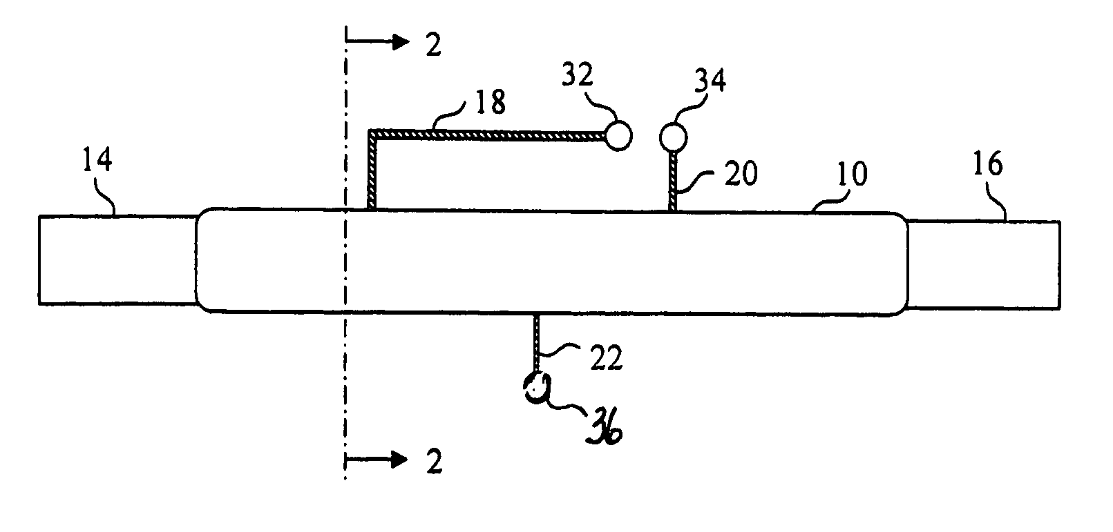
[0010] The present invention, based on Penning Ionization Electron Spectroscopy in glow discharge plasma, provides an analytical apparatus and method useful in detecting and identifying a wide range of chemical species present in a flowing gas mixture. The present invention measures the energy of electrons liberated by Penning Ionization in the afterglow of a gas discharge. The produced electron energy spectrum contains peaks specific for each component of the sample gas. Contrary to the above mentioned prior art technologies, Penning Ionization Electron Spectroscopy is relatively simple in implementation. The apparatus is similar to microplasma apparatus used in optical emission spectroscopy, mass spectroscopy, and ion mobility spectroscopy, but, in accordance with the present invention, such equipment, with a minimal extension for an additional electrode, incorporates a source and an analyzer in the same volume thus providing an opportunity for true integration in an on-chip gas analyzer. The technical simplicity of PIES (e.g., no optics or ultra-high vacuum is required) and the capability to directly identify various species with high sensitivity make it ideal for miniature analytical instrumentation for in situ applications.

Problems solved by technology

These sensors, although tiny and highly sensitive with a wide response range, do not provide sample identification information.
However, these units are technically complex, heavy and bulky, and require vacuum and high voltage for operation.
Presently, however, portable IMS devices used as in-field monitors experience a number of problems related mostly to poor selectivity and memory effects.
In addition, IMS instruments require significant amounts of carrier gas and require a source of ionization that complicates the design.

Method used


Image

  • Gas detection and identification apparatus and method
  • Gas detection and identification apparatus and method
  • Gas detection and identification apparatus and method

Examples


second embodiment

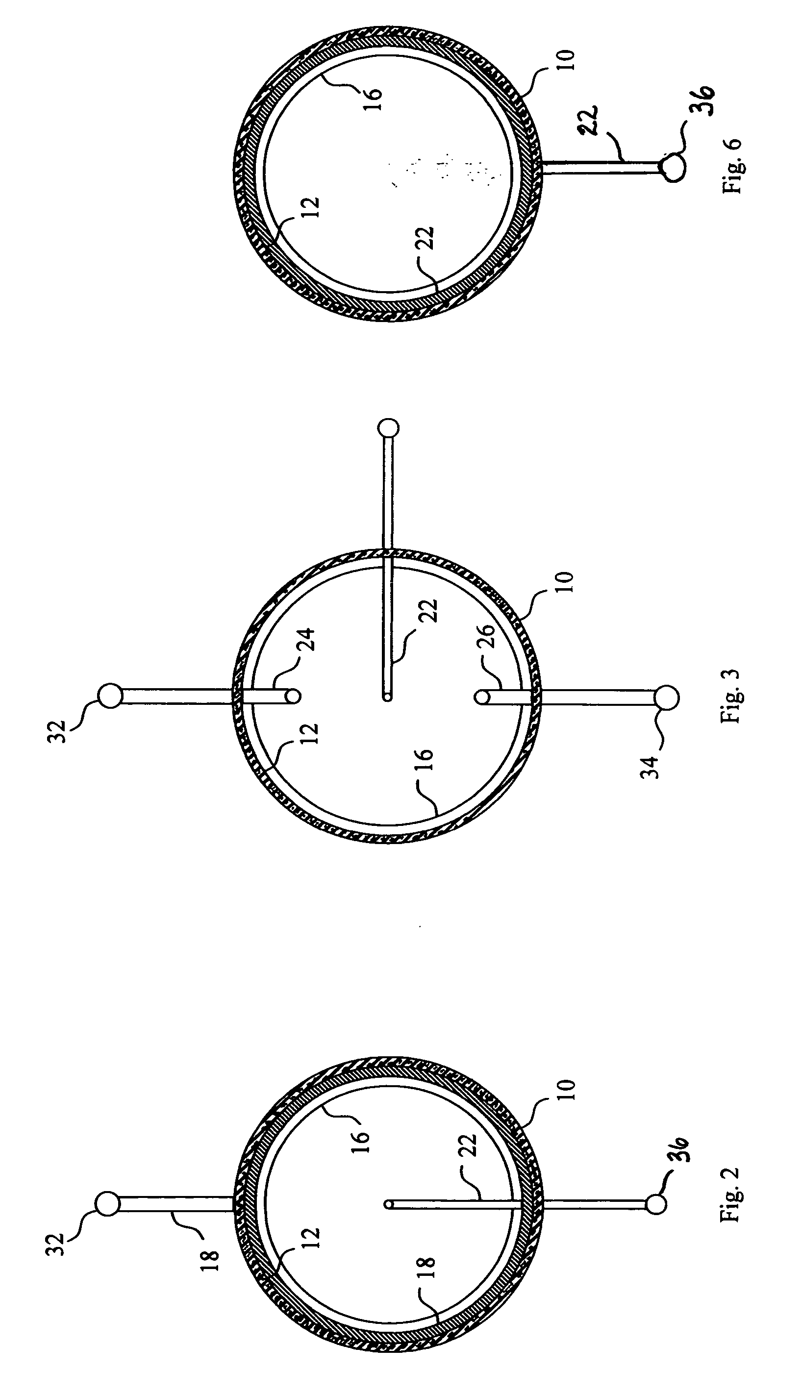
[0027]FIG. 3 is a sectional view of a gas detector constructed in accordance with the present invention. In the FIG. 3 embodiment of the present invention, each of the excitation electrodes 24 and 26 extends radially through the wall of elongated tube 10 from outside the elongated tube to through bore 12.

third embodiment

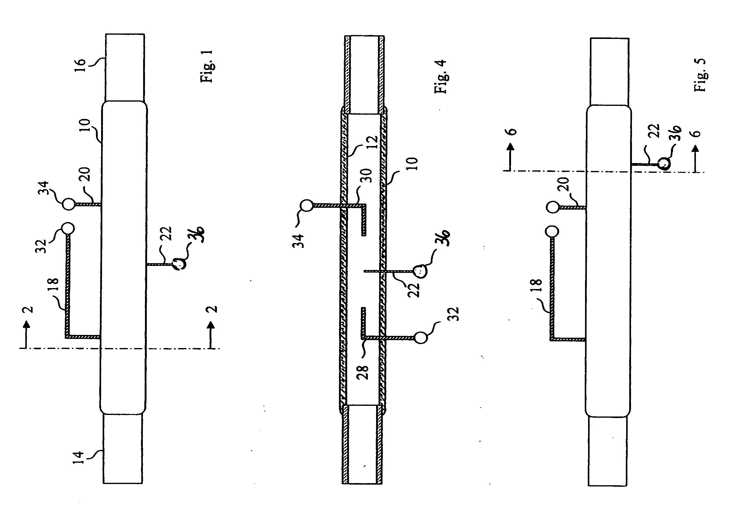
[0028]FIG. 4 is a sectional view of a gas detector constructed in accordance with the present invention. In the FIG. 4 embodiment of the present invention, each of the excitation electrodes 28 and 30 extends axially of through bore 12.

[0029] As indicated above, through bore 12 is free of recesses that would otherwise form dead spaces in which the mixture of the carrier gas and the analyte gas might be trapped undesirably. Thus, the anode electrode and cathode electrode of a gas detector constructed in accordance with the present invention should be flush with the surface of through bore 12 or extend into the through bore as illustrated in FIGS. 2, 3 and 4. In this way, the excitation electrodes are exposed to the flow of the mixture of the carrier gas and the analyte gas through bore 12.

[0030] Excitation electrodes 18 and 20 in FIGS. 1 and 2, excitation electrodes 24 and 26 in FIG. 3, and excitation electrodes 28 and 30 in FIG. 4 are adapted for connection to a source of excitation...


PUM


Abstract

Gas detection and identification apparatus that receives a flow of a mixture of a carrier gas and an analyte gas and detects and identifies the components of the flowing gas mixture by Penning Ionization Electron Spectroscopy (PIES).

Description

FIELD OF THE INVENTION [0001] The present invention relates, in general, to an apparatus and a method for detecting the presence of one or more gases in a flowing gaseous fluid and, in particular, to a gas detection apparatus and method that detects the presence of flowing gases and identifies these gases by Penning Ionization Electron Spectroscopy (PIES). BACKGROUND OF THE INVENTION [0002] In recent years, there has been a clear trend to downscale analytical instruments and to realize such instruments on the chip-based format. Examples can be found in every branch of analytical science, but this trend is especially important for gas analysis given the shear size of the field and the importance in science and engineering, industrial process control, improved environmental practices, aerospace applications, and other areas. Modern applications require the detection and identification of a wide variety of chemical species over vast concentration ranges. The analysis often must be carr...

Claims


Application Information

Patent Timeline
IPC IPC(8): G01N27/62
CPCG01N27/62
Inventor SHEVEREV, VALERY A.
Owner SHEVEREV VALERY A
Learn More