Multipath resolving correlation interferometer direction finding

a multi-path resolving and direction finding technology, applied in direction finders, multi-channel direction-finding systems using radio waves, instruments, etc., can solve the problems of large amplitude correlation side lobes, real potential for large errors, and degrade the reliability of the estimate of azimuth and elevation of the directly incident radar signal

Active Publication Date: 2007-11-29
BAE SYST INFORMATION & ELECTRONICS SYST INTERGRATION INC
View PDF8 Cites 60 Cited by
  • Summary
  • Abstract
  • Description
  • Claims
  • Application Information

AI Technical Summary

Problems solved by technology

However, simply increasing DF aperture sizes without increasing the number of DF antennas leads to large amplitude correlation side lobes and a real potential for large errors.
A basic problem has been to use such a prior art DF interferometer system to locate the elevation and azimuth of a transmitter, such as a radar transmitter, mounted on an aircraft that is flying at low altitudes above water.
Signals transmitted from the aircraft mounted radar received by line of sight and reflected from the surface of the water introduce multi-path error into both azimuth and elevation measurements and degrade the reliability of the estimate of the azimuth and elevation of the directly incident radar signal.
In the presence of multi-path effects, the wave fronts of the received signal are distorted so that the gradients of a wave front at a given location may be erratic and inconsistent with respect to the location of the signal source.
In addition, either a phase comparison interferometer or an amplitude comparison direction-finding system over a reflecting surface such as seawater will result in multi-path caused errors in the measurement of signal direction-of-arrival.
It does not and cannot resolve multi-path signals, such as reflected from the surface of the ocean, but identifies the most probable incident wave arrival angle based on previous interferometer array calibrations.

Method used


Image

  • Multipath resolving correlation interferometer direction finding
  • Multipath resolving correlation interferometer direction finding
  • Multipath resolving correlation interferometer direction finding

Examples


Embodiment Construction

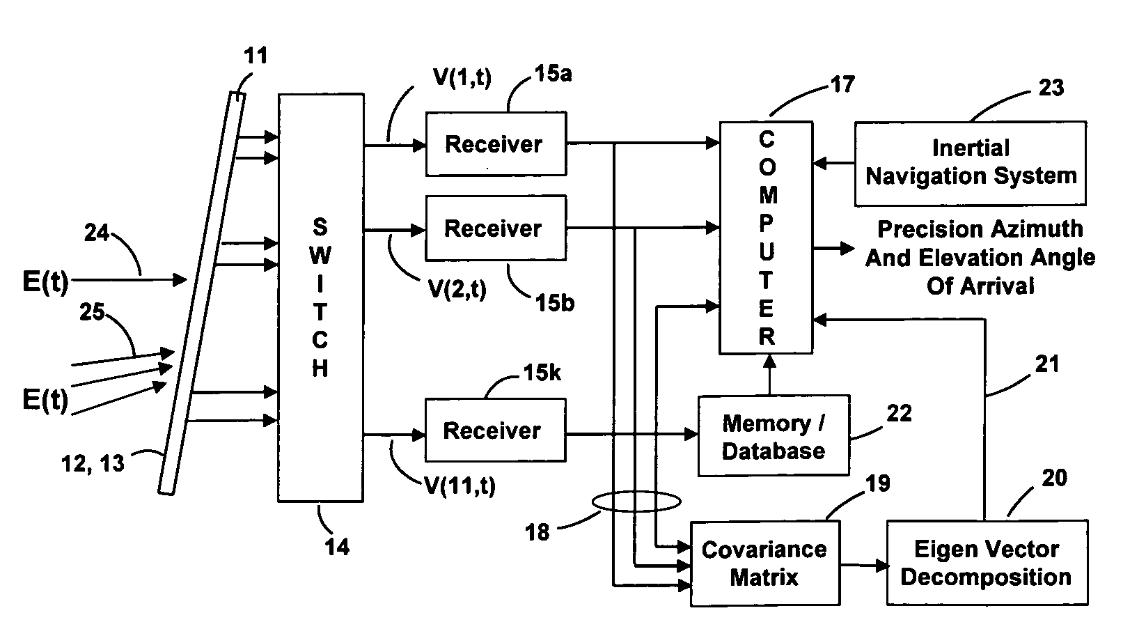
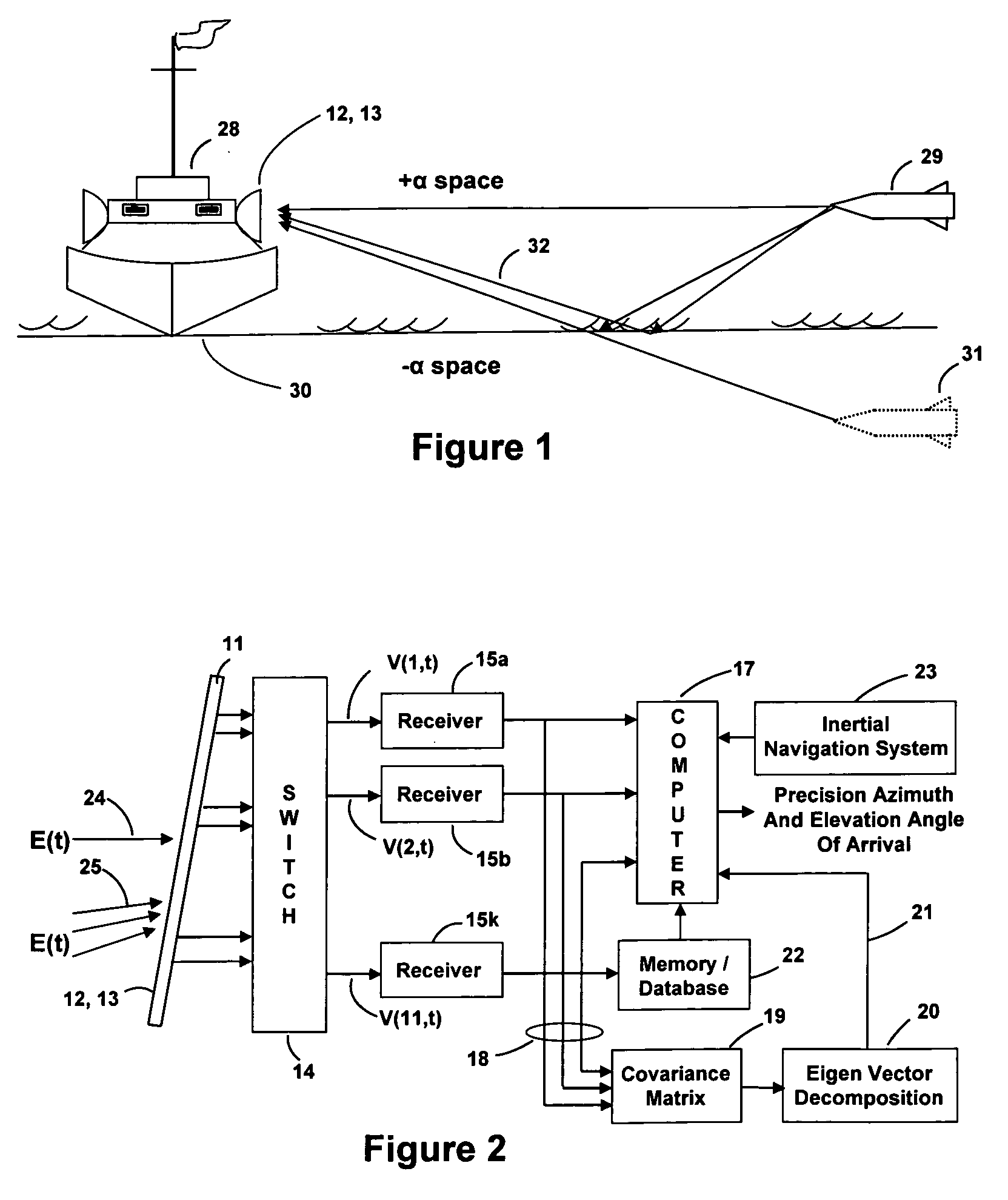
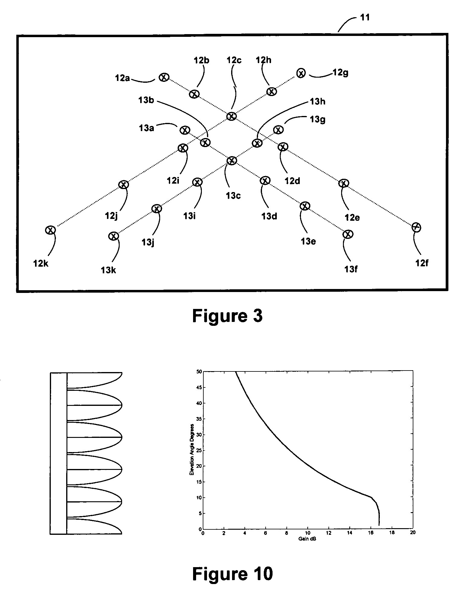
[0035]In the following detailed description and the drawings there are numerous terms used that are defined below:[0036]Apol (α,β) are the calibration vectors as a function of α (the elevation angle) and β (the azimuth angle) where:[0037]Apol=Av(vertical) or Ah (horizontal) calibration array manifold data base.[0038]+α=the space above the surface of the water.[0039]−α=the space below the surface of the water.[0040]CIDF=Correlation Interferometer Direction Finding.[0041]MR-CIDF=Multipath Resolving Correlation Interferometer Direction Finding[0042]DF=direction finding.[0043]DOA=direction of arrival, and consists of both the azimuth angle β and elevation angle α of a received signal.[0044]E=electromagnetic radio waves incident on the array of antennas.[0045]Na=number of antennas in each beam forming / direction finding array, eleven herein.[0046](i, q)=in-phase and quadrature-phase of a complex quantity.[0047]Rxx=measured covariance matrix.[0048]λ=eigenvalues of the measured covariance m...


PUM


Abstract

Apparatus and a method utilizing correlation interferometer direction finding for determining the azimuth and elevation to an aircraft at long range and flying at low altitudes above water with a transmitting radar while resolving multipath signals. The signals from the radar are received both directly and reflected from the surface of the water using horizontally polarized and vertically polarized antenna arrays, are digitized and are stored in separate covariant matrices. Eigenvalues for the eigenvectors of the matrices processed on signal samples recorded on horizontally polarized X arrays are compared to the eigenvalues for the eigenvectors of the covariance matrices processed on signal samples recorded on vertically polarized X arrays. Incident field polarization is associated with the antenna array measurements that yield the strongest eigenvalue. The eigenvector and eigenvalues for the strongest signal are selected and used for subsequent signal processing. An initial global search assuming mirror sea-state reflection conditions using the signal eigenvector having the strongest eigenvalue is performed to yield an approximate elevation α and azimuth β to the aircraft. The approximate values are then used as the starting point for a subsequent conjugate gradient search to determine accurate elevation α and azimuth β to the aircraft.

Description

FIELD OF THE INVENTION[0001]The present invention relates to a correlation interferometer that resolves radar signals received directly from a transmitter on an aircraft flying at low altitudes above the water and severe multi-path radar signals from the same transmitter reflecting from the surface of the water to obtain the azimuth and elevation of the signal while resolving multipath effects.BACKGROUND OF THE INVENTION[0002]A typical DF interferometer system locates the direction to a remote transmitter by utilizing the phase difference of the transmitter signal arriving at the individual antennas. DF accuracy of such systems is directly related to DF array aperture size which is determined by the spacing between multiple antennas of an antenna array of the DF system. All other things being equal, larger DF apertures increase direction of arrival (DOA) accuracy. However, simply increasing DF aperture sizes without increasing the number of DF antennas leads to large amplitude corre...

Claims


Application Information

Patent Timeline
Patent Type & Authority Applications(United States)
IPC IPC(8): G01S13/72G01S7/40
CPCG01S3/74G01S3/146
Inventor STRUCKMAN, KEITH A.MARTEL, ROBERT T.
Owner BAE SYST INFORMATION & ELECTRONICS SYST INTERGRATION INC
Why Eureka
Try Eureka