Silicon Substrate and Method of Forming the Same

a technology of silica glass and substrate, applied in the field of silicon substrate, can solve the problems of describing nothing about the variation in the expansion coefficient of silica glass, and the further decrease of the melting temperature of fluorine, so as to prevent the occurrence of defects

Inactive Publication Date: 2007-11-29
HAMAMATSU PHOTONICS KK +1
View PDF3 Cites 6 Cited by
  • Summary
  • Abstract
  • Description
  • Claims
  • Application Information

AI Technical Summary

Benefits of technology

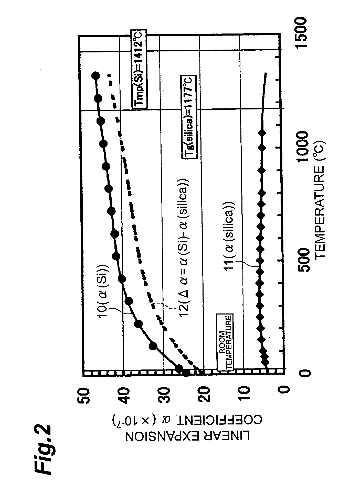
[0007] Each of the papers cited above details the decrease of Tg by addition of alkaline metal impurities and the effect of decreasing the minimum transmission loss of optical fiber by the decrease of Tg. However, they describe nothing about the variation in the expansion coefficient of silica glass with addition of impurities and the effect thereof. In addition, they highlight the effect of largely decreasing Tg by addition of a small amount of an alkali metal oxide or an alkaline earth oxide in silica glass, and also point out that there is no precedent for addition of a small amount of not more than about several % of these impurities.
[0018] An object of the present invention is to obtain a silicon substrate in which internal strain is reduced between glass and silicon crystal, and to establish a method of forming the silicon substrate.
[0029] The silicon substrate forming method, as described above, preferably has a step of effecting the temperature decrease according to the predetermined program after the oxidation and densification of the porous silicon. This is effective for prevention of occurrence of defects such as cracks, fissures, or peeling in glass, as compared with a quenching case from the heat treatment temperature.

Problems solved by technology

However, they describe nothing about the variation in the expansion coefficient of silica glass with addition of impurities and the effect thereof.
It also reports that doping of the borophosphate silicate glass with fluorine further decreases the melting temperature.

Method used


Image

  • Silicon Substrate and Method of Forming the Same
  • Silicon Substrate and Method of Forming the Same
  • Silicon Substrate and Method of Forming the Same

Examples


examples

[0066] Described below in detail with examples are cases of applying the Group 1a alkali metal oxides such as Li2O, Na2O, K2O, Rb2O, and Cs2O and the Group 2a alkaline earth oxides or the like such as MgO, CaO, SrO, and BaO being the network modifiers (NWM), to the present invention.

[0067] These alkali metals or alkaline earth metals react with various acids to form salts. Typical examples of the acids herein include hydrides of the halogen family of elements such as fluorine, chlorine, bromine, and iodine, nitric acid, sulfuric acid, phosphoric acid, boric acid, carbonic acid, oxalic acid, and so on. It is known that the salts of the above metals and the acids are dissolved in various solvents. Described below in particular are cases where the solvent is water. All of these salts are well dissolved in water. Particularly, an aqueous solution of nitrate or sulfate does not dissolve porous silicon (PS) or porous silica, and, therefore, they are particularly preferred salts in implem...


PUM

PropertyMeasurementUnit
glass transition temperatureaaaaaaaaaa
transmission loss wavelengthaaaaaaaaaa
viscosityaaaaaaaaaa

Abstract

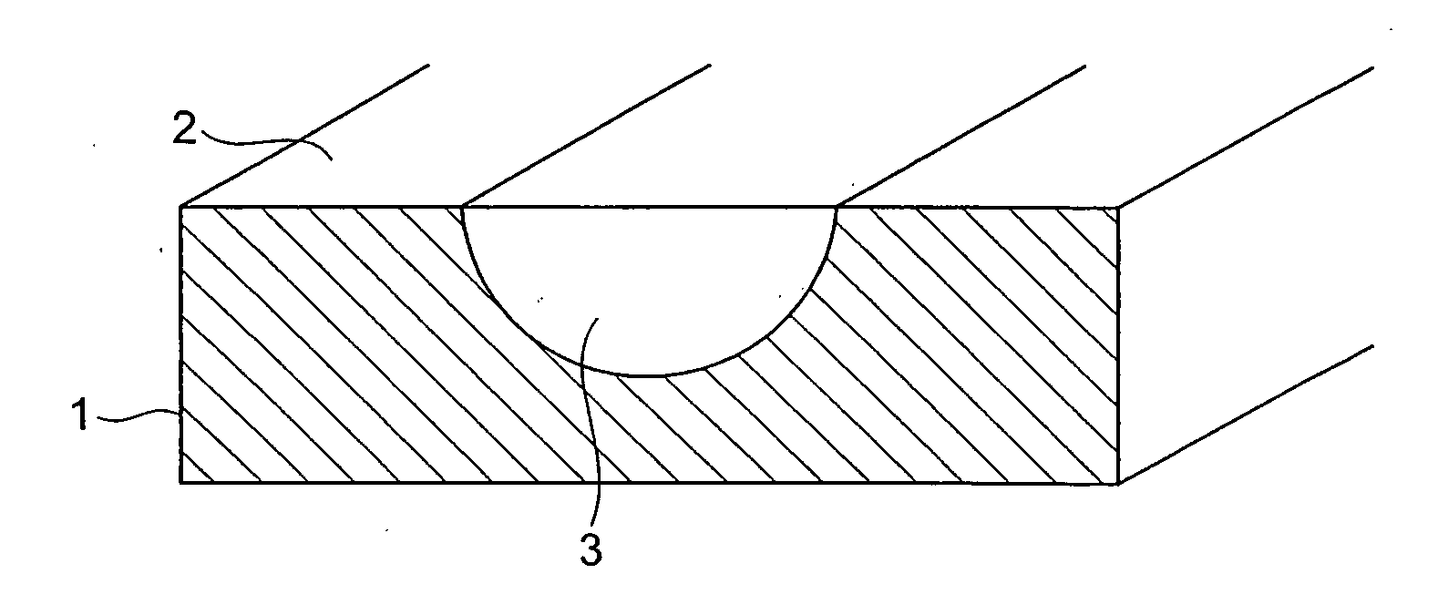
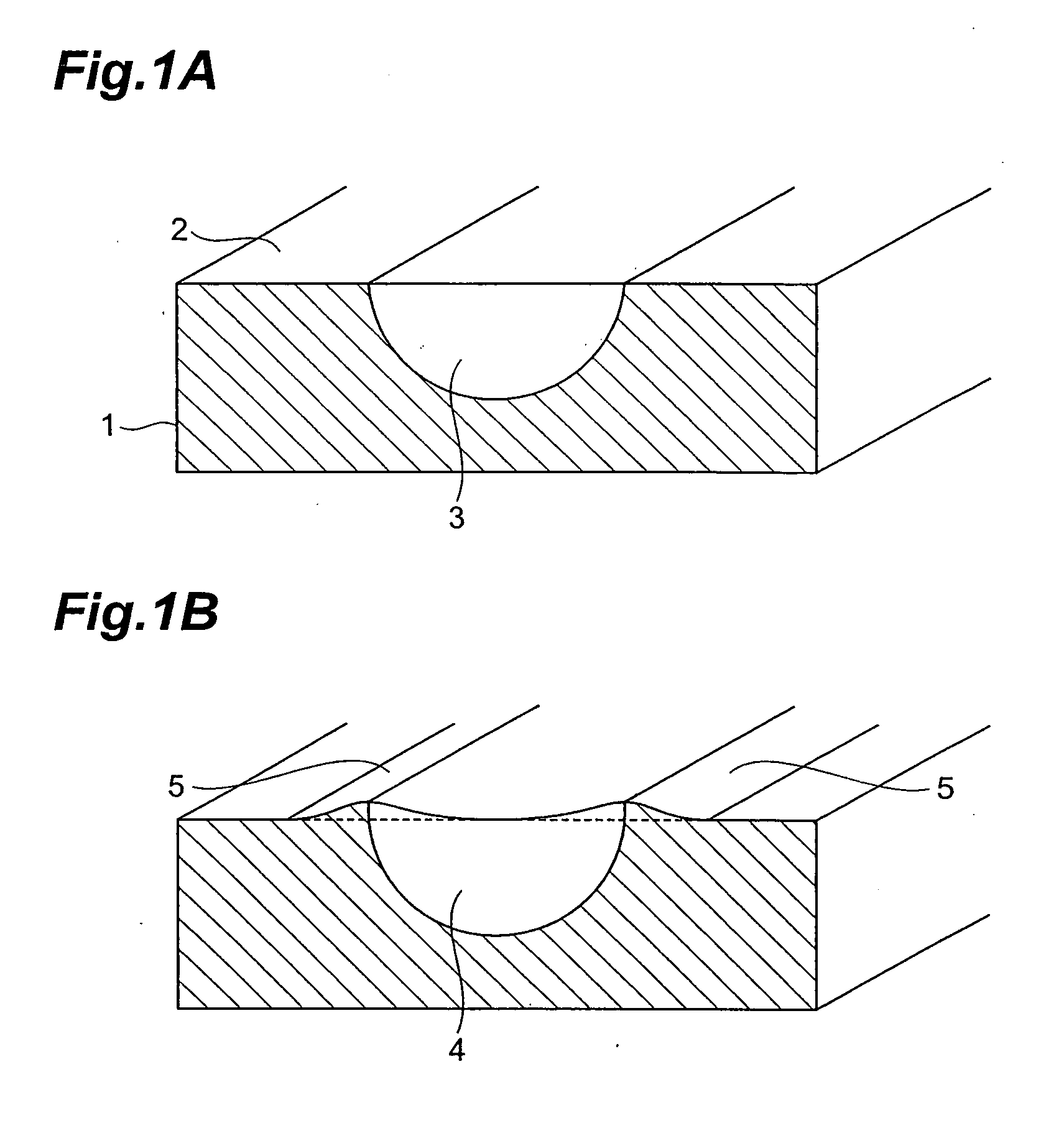
A silicon substrate 1 has a structure in which a depression of a silicon crystal is formed on at least one principal surface 2 side of a crystalline silicon substrate and which has a vitreous region 3 filled in the depression and consisting primarily of silicon oxide. The vitreous region 3 is formed so that the glass transition temperature Tg thereof is lower than that of pure silica glass and not more than 900° C. This configuration realizes the silicon substrate in which internal strain is reduced between glass and the silicon crystal, and a forming method thereof.

Description

TECHNICAL FIELD [0001] The present invention relates to a silicon substrate and a forming method thereof and, more particularly, to a silicon substrate in which a depression of a silicon crystal is formed on at least one principal surface of the silicon substrate and in which the depression is filled with a vitreous material, and a method of forming a silicon substrate, comprising forming a mask layer on the silicon substrate; anodizing the silicon substrate with the mask layer removed in part, in a hydrofluoric acid solution, or placing the silicon substrate in a gas phase containing fluorine, thereby selectively forming a porous silicon (PS) region around the removed part of the mask layer; partially or completely oxidizing a silicon fine column inside this PS region to form a porous region containing silica; doping the porous region containing silica, with an impurity element; and performing a thermal treatment to form the silicon substrate wherein the PS-existing region is fille...

Claims


Application Information

Patent Timeline
Patent Type & Authority Applications(United States)
IPC IPC(8): B32B9/04C03B19/08G02B6/12G02B6/122G02B6/13
CPCB82Y20/00G02B6/1223G02B2006/121G02B2006/12061G02B6/13Y10T428/31663
Inventor NAGATA, SEIICHI
Owner HAMAMATSU PHOTONICS KK
Why Eureka
Try Eureka