

Photocatalyst Particle Body
- Summary
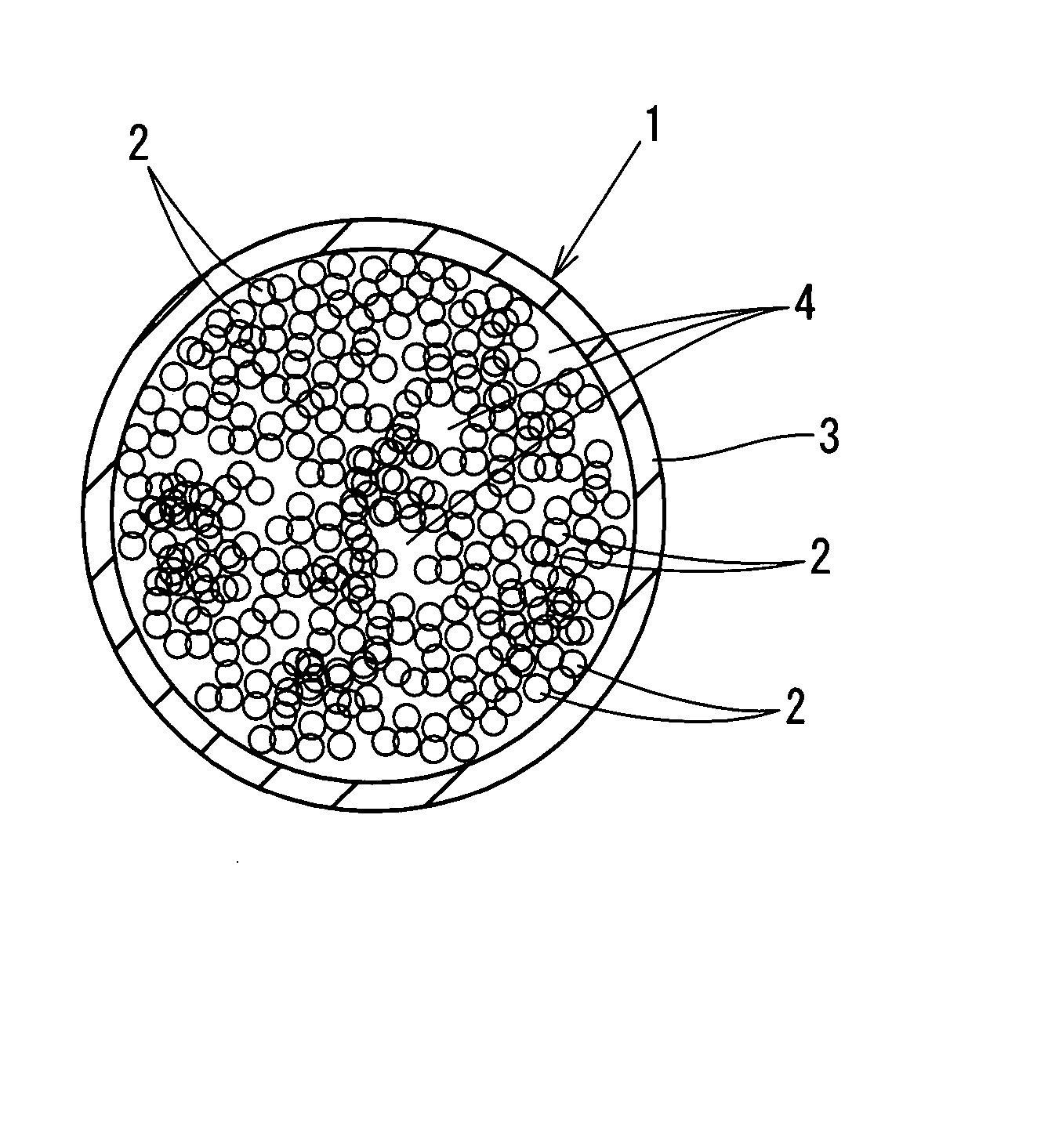
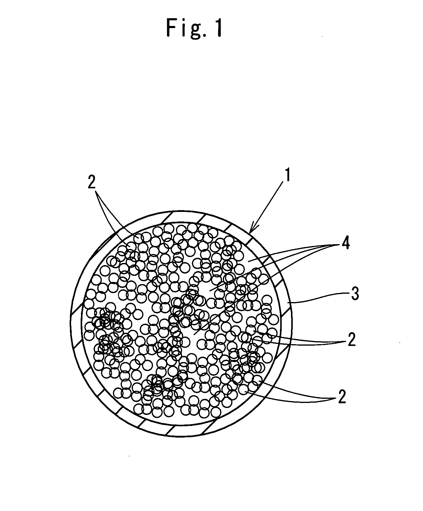
- Abstract
- Description
- Claims
- Application Information
AI Technical Summary
Benefits of technology
Problems solved by technology
Method used
Image

Examples
first embodiment
[0034] 200 grams of dichloromethane was put in a beaker, and while stirring dichloromethane by a stirring magnet by using a stirrer, 17.4 grams of polystyrene (pellet with 3 millimeter diameter×3 millimeter length, made by Kishida Chemical Co., Ltd.) was put into the beaker and dissolved in dichloromethane in about 1 hour, whereby a polystyrene solution with a concentration of 8 weight percent was obtained. Dichloromethane evaporates even at a room temperature, so that during dissolving, a polyvinylidene chloride film (registered trademark: Saran Wrap) was covered on the mouth of the beaker and the periphery thereof was stopped with a rubber band to prevent evaporation of dichloromethane.
[0035] While 30 ml of the apatite-coated titanium dioxide fine particle slurry (slurry in which apatite-coated titanium dioxide obtained by coating 20% of the surface of titanium dioxide ST21 made by Ishihara Sangyo Kaisha, Ltd. (average particle size: 20 nanometers) with apatite is dispersed at a ...
PUM
| Property | Measurement | Unit |
|---|---|---|
| Length | aaaaa | aaaaa |
| Length | aaaaa | aaaaa |
| Length | aaaaa | aaaaa |
Abstract
Description
Claims
Application Information