Abnormality determination device of cylinder pressure sensor

a technology of cylinder pressure sensor and abnormality determination, which is applied in the direction of electrical control, instruments, brake systems, etc., can solve the problems of difficult to handle the abnormality in the gain, abnormal offset, and more serious abnormalities in the gain, so as to reduce the possibility of significant disturbance in the control

a technology of cylinder pressure sensor and abnormality determination, which is applied in the direction of electrical control, instruments, brake systems, etc., can solve the problems of difficult to handle the abnormality in the gain, abnormal offset, and more serious abnormalities in the gain, so as to reduce the possibility of significant disturbance in the control

US20070277591A1Inactive Publication Date: 2007-12-06DENSO CORP

Image

  • Abnormality determination device of cylinder pressure sensor
  • Abnormality determination device of cylinder pressure sensor
  • Abnormality determination device of cylinder pressure sensor

Examples


Embodiment Construction

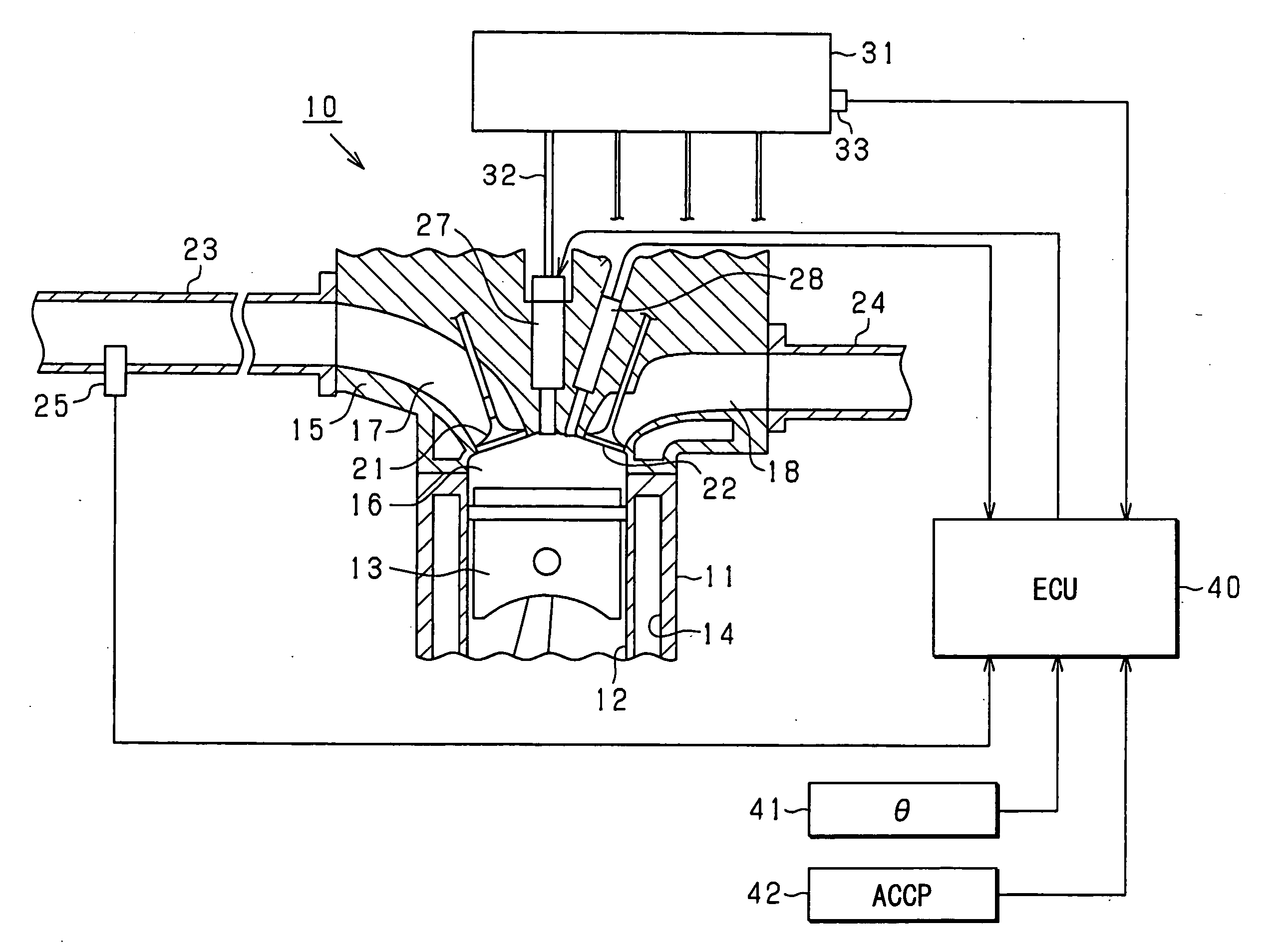
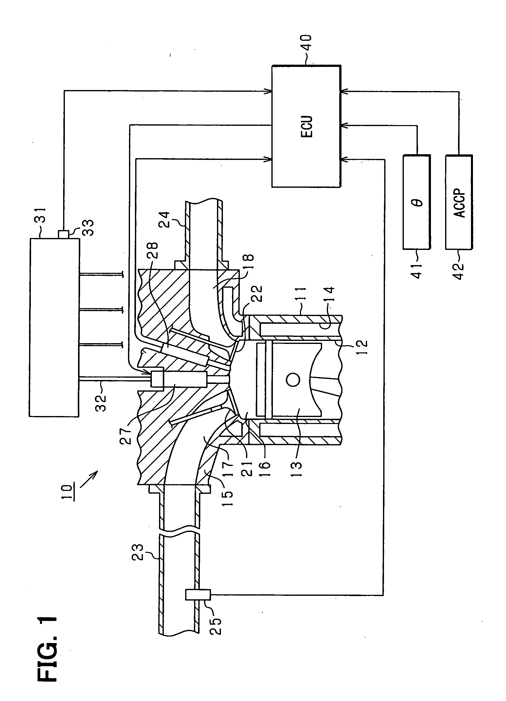
[0024]Referring to FIG. 1, a common rail fuel injection control system of a vehicular diesel engine according to an embodiment of the present invention is illustrated. FIG. 1 is a schematic diagram showing a vehicle control system, to which an abnormality determination device of a cylinder pressure sensor according to the present embodiment is applied. As shown in FIG. 1, the system includes an internal combustion engine 10 as the diesel engine, various sensors and an ECU 40 (electronic control unit) for controlling the engine 10, and the like.

[0025]The engine 10 is structured such that pistons 13 are accommodated in cylinders 12 (only one cylinder is illustrated in FIG. 1 for the sake of simplicity) formed in a cylinder block 11 and a crankshaft as an output shaft (not shown) is rotated by reciprocation of the pistons 13. A coolant channel 14 is formed in the cylinder block 11 to cool the engine 10 with a coolant. A cylinder head 15 is fixed to an upper end face of the cylinder blo...


PUM

PropertyMeasurementUnit
pressureaaaaaaaaaa
pressuresaaaaaaaaaa
combustion pressureaaaaaaaaaa

Abstract

An abnormality determination device of a cylinder pressure sensor calculates a gain (sensing sensitivity coefficient) and an offset (bias) indicating an output characteristic of the cylinder pressure sensor. The device determines existence or nonexistence of an abnormality in the gain and the offset respectively. When the device determines that the abnormality exists, the device performs failsafe processing set in modes different from each other between the case of the abnormality in the gain and the case of the abnormality in the offset. As the failsafe processing in the case of the abnormality in the gain, the device performs processing for substantially prohibiting usage of a sensor value of the cylinder pressure sensor in control (fuel injection timing control) by using an alternative value (specified value) instead of the sensor value of the cylinder pressure sensor.

Description

CROSS REFERENCE TO RELATED APPLICATION[0001]This application is based on and incorporates herein by reference Japanese Patent Application No. 2006-149231 filed on May 30, 2006.BACKGROUND OF THE INVENTION[0002]1. Field of the invention[0003]The present invention relates to an abnormality determination device for determining existence or nonexistence of an abnormality in a cylinder pressure sensor that senses cylinder pressure of an internal combustion engine.[0004]2. Description of Related Art[0005]An engine (internal combustion engine) combusts a mixture gas in a combustion chamber and works by depressing a piston with combustion pressure. Therefore, the combustion pressure is a parameter directly indicating a combustion state. If the combustion state is grasped, estimation of a fuel injection amount or combustion temperature, detection of knocking, detection of a peak position of the combustion pressure, detection of misfire and the like are enabled. Therefore, the combustion press...

Claims


Application Information

Patent Timeline
06 Dec 2007
Publication
US20070277591A1
IPC
G01L23/22; G01M19/00; G01M99/00
CPC
F02D35/02; Y02T10/40; F02D41/222; F02D35/023; F02D2041/281
Inventors
HOSHI, SHINYA; HARAGUCHI, HIROSHI